HiFiCompass
Purifi Audio PTT6.5W04-01A midwoofer
What is on the test bench?
The famous expression "All roads lead to Rome" in the context of today should read "All roads lead to Denmark". I will not be mistaken if I say that most home speakers up to the very top class are currently being assembled using speaker drivers with Danish roots. Judge for yourself:
- Peerless
- Vifa
- ScanSpeak
- SB Acoustics
- Dali
- Dynaudio
- Wavecor
- Timphany
- Audiotechnology
- PointSource Acoustics
- this is not a complete list of Danish companies or companies rooted in the Danish past. And today this list has replenished with an one more very young brand - PURIFI.
PURIFI - it is an association of successful and world-famous audio-nthusiasts-professionals whose the main goal is, attention (!) - overcoming of existing quality barriers and creating the best audio products in the world. You can get familiar with the history of the company here, but now it’s just worth mentioning the people who lead this team:
- Bruno Putzeys, Co-Founder
Inventor of UcD (Philips), probably still the most widely used class-D amplifier for upmarket audio products. Inventor of Ncore (Hypex), which is generally considered the first class-D amplifier to successfully compete with class-A on audio performance. Developed high performance A/D and D/A converter designs for Grimm and Mola-Mola. Co-founder for Kii Audio. Holds 8 patents and multiple patent disclosures
- Lars Risbo, Co-Founder
Pioneered direct switching PCM-PWM audio amplifiers as founder of Toccata Technology, later acquired by Texas Instruments. Elected TI Fellow (2012) and Audio CTO (2013). Research interests include digital signal processing, system-level and signal chain optimization, oversampled data converters, transducers and mixed-signal architectures. Ph.D from DTU (1994). Holds >30 US granted patent families
- Carsten Tinggaard, Co-Owner (PURIFI Transducer Technology)
Founder and owner of PointSource Acoustics (2009). Previously Product Manager for Danish Sound Technology (2003) and CTO of Tymphany Denmark (2005) responsible for establishing R&D Denmark facility covering Peerless, Vifa and Scan-Speak brands. Spearheaded Peerless tech. transfer to China manufacturing facilities. Co-owner of PURIFI Transducer Technology (2017), a subsidiary of PURIFI
- Peter Lyngdorf, Co-Founder
Owner of Lyngdorf Family Holding, Hi Fi Klubben, DALI and Steinway Lyngdorf. The group has >1000 employees and multiple factories in Denmark and China. Former owner several audio companies including NAD Electronics and Snell Acoustics. Driver of Digital Room Compensation technology from Snell DSP 1000 (1993) through NAD, TacT Audio and now Lyngdorf RoomPerfect
- Claus Neesgaard, Co-Owner, Director
Held Business/R&D Management, Product Definer and Systems Architect roles (Texas instruments) responsible for launching and growing TI’s TAS/TPA-series class D amplifier portfolio. Stints as head of TI’s Audio DSP product line, leading the transition into streaming-based system solutions. In early career, developed several core innovations in class D amplification for Toccata Technology leading to the acquisition by TI in 2000. M.Sc.E from DTU (1998). Holds 6 US patents
- Kim Madsen, Applications Manager
Specialized in audio and power electronics. Held roles as Applications Manager, Product Definer and Lead Systems Engineer (Texas Instrument) most recently focused on TI’s Automotive Amplifier portfolio. Developed mil-spec power modules for the Ariane 5 Rocket (Alcatel) and several fighter aircrafts (Dynatech). M.Sc.EE (1991) from DTU. Holds 5 US patents and several patent disclosures
- Søren Poulsen, R&D
Held roles as Product Definer and Lead Systems Engineer (Texas Instruments) especially focused on performance- and reliability optimization of TI’s mid/high power Audio IC’s. Owned definition and architecture development of worlds highest-power, highest-performance Integrated Circuit (IC) Amplifier. Ph.D from DTU (2004). Holds 5 US patents and several publications
- Morten Halvorsen, R&D Acoustics (PURIFI Transducer Tech.)
Worked as Senior Acoustic Engineer at PointSource Acoustics. Co-developed both the loudspeakers and sound unit of the Montana Sound and SoundBy PointSource products. Specialized in electromagnetic simulations, measurements and procedure optimization. Researched force factor modulation, developing measurement equipment and simulation models. Results presented at AES 138. M.Sc.E.E. with specialization in acoustics from DTU (2014)
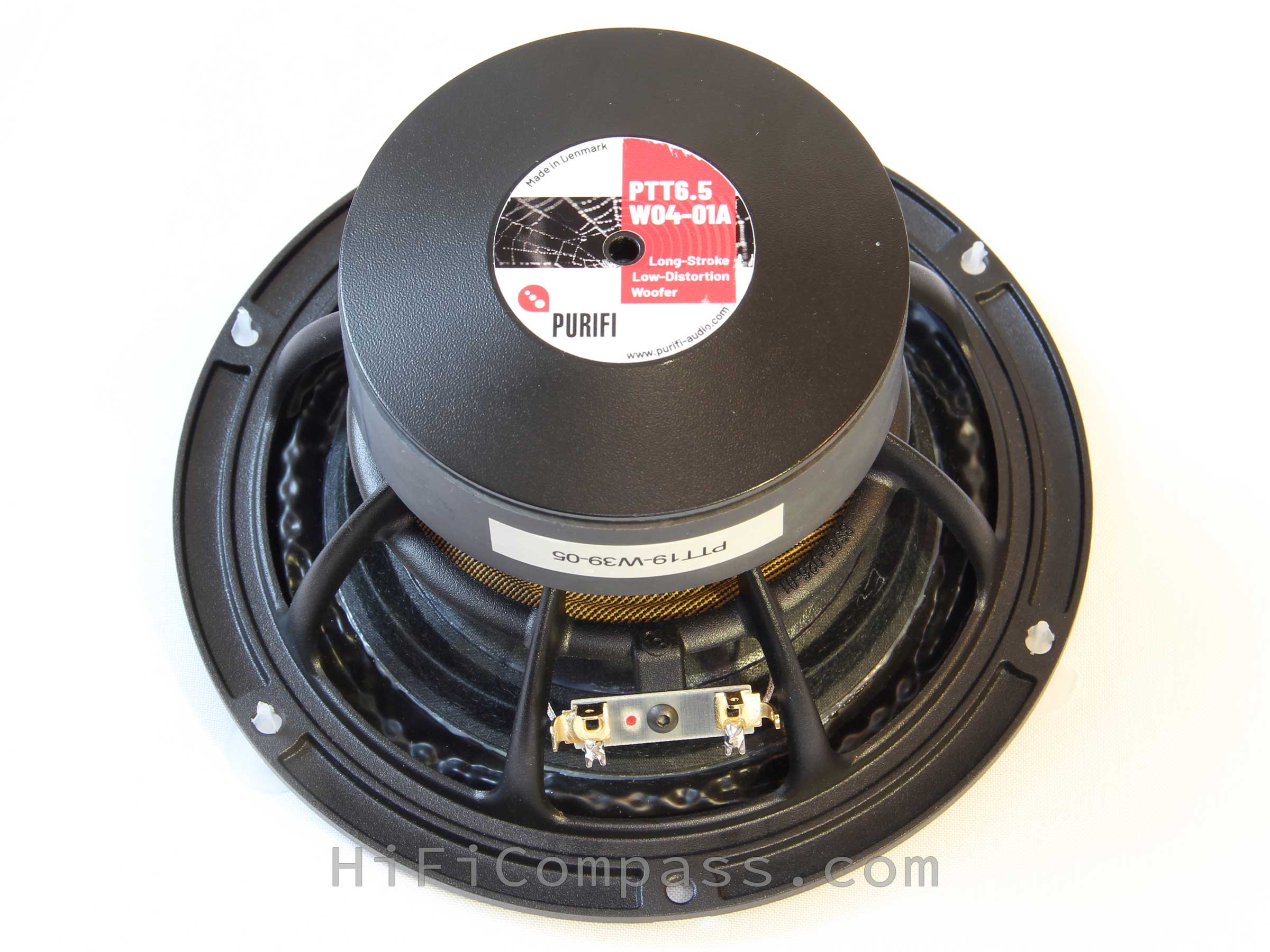
The company debuted in Munich (Germany) in May 2019 having presented its first products that impressed with their characteristics - the class-D 1ET400A amplifier module and the PTT6.5W04-01A midwoofer. As a rule, any company tries to start with its best product in order to demonstrate its technical level and potential, otherwise death on takeoff may result. Today its midwoofer has already reached us. Well, let's see from where the company takes its start.
Why do we test this?
It is always interesting to get acquainted with new products, especially new brands, as well as with such ambitious declared characteristics. Therefore, my interest is absolutely sincere.
I express my deep gratitude to the PURIFI company, as well as personally to its co-owner and developer Lars Risbo for the speaker samples PTT6.5W04-01A provided for testing and the time spent discussing the technical aspects related to the design and technical solutions applied in the speakers. Further in the text on a highlighted background I will be quoting a little from our dialogue for explaining some points.
What did the manufacturer state?
The PTT6.5W04-01A is a 6.5” driver that truly cracks the long-stroke code. PURIFI’s research has identified the parameters that have so far prevented long stroke drivers from breaking through in truly high performance audio. The distortion of the acoustic output of a driver is a combination of several separate distortion mechanisms in the motor, cone and suspension. When testing a complete driver with sine waves, a situation often arises where a small tweak seemingly improves harmonic distortion (HD) by letting two mechanisms counteract each other. This always leads to a clear worsening of intermodulation distortion (IMD) that becomes obvious when testing the unit with a more complex signal. This is why traditional HD tests fail to predict subjective sound quality.
PURIFI takes care to optimize the various distortion mechanisms separately, thus guaranteeing that any measured improvement truly reflects a real audible improvement no matter what the signal is. Accurate mathematical models are developed for the motor, suspension and the vibroacoustics of the dome and surround. These models clearly explain several distortion mechanisms in each domain, which provides fundamental insights into better ways of constructing the motor, cone and suspension. Finally, the same models are used to numerically fine-tune the geometry. This way of working reliably reduces multiple distortions mechanisms which secures low IMD for complex signals.
- Low Force Factor Modulation
- Prevents voice coil current from modulating Force Factor (Bl). The PURIFI motor completely avoids this classical Achilles’ heel of long stroke drivers. This translates into low intermodulation (IMD): clean, undistorted midrange even in the presence of a heavy bass.
- Equates to low impedance modulation, meaning that drive current is not distorted by cone motion.
- Very Constant Force Factor over Excursion
- Prevents voice coil position from modulating the force factor. This is the classical cause of “burbling” i.e. amplitude modulation of the midrange by large low-frequency cone excursions.
- Low Surround Radiation Distortion
- The surround contributes to sound output. Conventional surrounds produce distortion as they deform. PURIFI’s Neutral Surround geometry avoids this mechanism without constraining motion. This reduces harmonic distortion as well as intermodulation distortion.
- Low Magnetic Hysteresis Distortion
- Hysteresis means that magnetic domains in iron retain traces of previous magnetization / demagnetization cycles which cause distortion when magnetized or demagnetized again. This distortion masquerades as benign harmonic distortion when tested with a sine wave but takes on a crackling or noisy character with more complex signals.
- Removing hysteresis distortion translates into a very “fluid” presentation with excellent front/back separation in the stereo image and a perfectly black background between instruments.
- Cleaner than large-cone short-stroke drivers
- The combination of the above characteristics results in a compact long-stroke driver that delivers complex sound with a clarity and lack of effort that was previously the exclusive province of large-cone short-stroke drivers. Additionally, thanks to the small cone size, the driver has excellent midrange reproduction. It is highly suited for two-way systems.
_1.jpg)
_2.jpg)
_3.jpg)
_4.jpg)
It should be noted, quite bold statements. Cracking the “long-stroke code” and making a "long-stroker" with a small membrane and sound like a big "short-stroker" is something new.
The preliminary data are very detailed and replete with completely new "pictures" that no speaker manufacturer has ever showed. A word spoken is past recalling. Therefore, publishing an excessive amount of all kinds of graphs and diagrams imposes certain obligations on a manufacturer and testifies to his confidence in his rightness. He is afraid of nothing and eagerly demonstrates the benefits of his product. It is a great rarity.
Of the midwoofer features the following should be noted:
- A four-layer voice coil - usually this is found only in true woofers or subwoofers but not in high fidelity midwoofers with a pretension on high quality midrange reproduction. As an exception I can remember the ScanSpeak Illuminator 15WUxxxx/18WUxxxx speaker series only.
- Impressive power handling - 100 W (noise) and 350 W(!) (IEC)
- Inductance 0.38 mH - well, not so much actually
- High mechanic quality factor Qm=8.3
- Modest sensitivity - 88.2 dB/2.83 Volt*1m
- A linear stroke of 10mm (!) at one direction - is a very high value, a really long-stroke one. Something that I've not seen in midwoofers with the Sd area of 133 cm2
- Yes, the voice coil is already 24 mm long and the working gap is 4 mm only
- The Mms is already 26.8 grams ... It will begin now ... I already hear - what? 6.5" with such a mass? Yes, the only place for it is in a compact car subwoofer, what are the midrange frequencies we can talking about?!
Here is a comments from the manufacturer regarding the last feature:
Lars Risbo : The 24mm Ø39mm 4 layer coil is responsible for the higher moving mass. It adds about 10g compared to a shorter 2 layer coil of a typical medium stroke 6.5” midwoofer. The paper cone is actually lighter than typical polypropylene or aluminum cones. The larger coil gives the benefit of high Bl and power handling which enables operation in small sealed boxes with use of lots of bass extension EQ. Since we also achieve very low coil inductance Le then the midrange response is uncompromised, i.e., the driver is still very ‘fast’ despite its higher moving mass. It’s like sportscars: the top speed is set by its power and friction/drag not by its mass (a Bugatti Chiron is about 2 tons of mass yet extremely fast). However, a bigger motor is more heavy – the same applies for speakers
Yes, the combination of parameters is very unusual. Let's see what the measurements show ...
Fig. 1 - shows the behavior of the force factor and the suspension stiffness depending on the voice coil displacement. If the stiffness curve is not surprising, then the almost flat dependence BL (x) deserves respect. Something is done right in the motor.
Fig. 3 - shows very low harmonic distortion in sound pressure
Fig. 4 - voice coil current harmonic distortion - above 100 Hz is very impressive, though there is nothing to compare this type of measurements with, no one manufacturer publishes this. But the fact of such a low level of distortion indicates a very good motor.
Fig. 6 - one more way to look at distortion depending on the frequency and signal level. At the sound pressure level of 100 dB, the 2nd harmonic does not exceed -50 dB, and the third is -62 dB at a frequency of 1 kHz. That's cool!
Visual inspection
 |
 |
 |
 |
 |
 |
So,
- Workmanship - all at the highest level. No traces of glue, scratches, dirt or dust. No spots and dents on the cone. No chips on the ferrite magnet and no gaps and skewness anywhere. There is nothing to complain about.
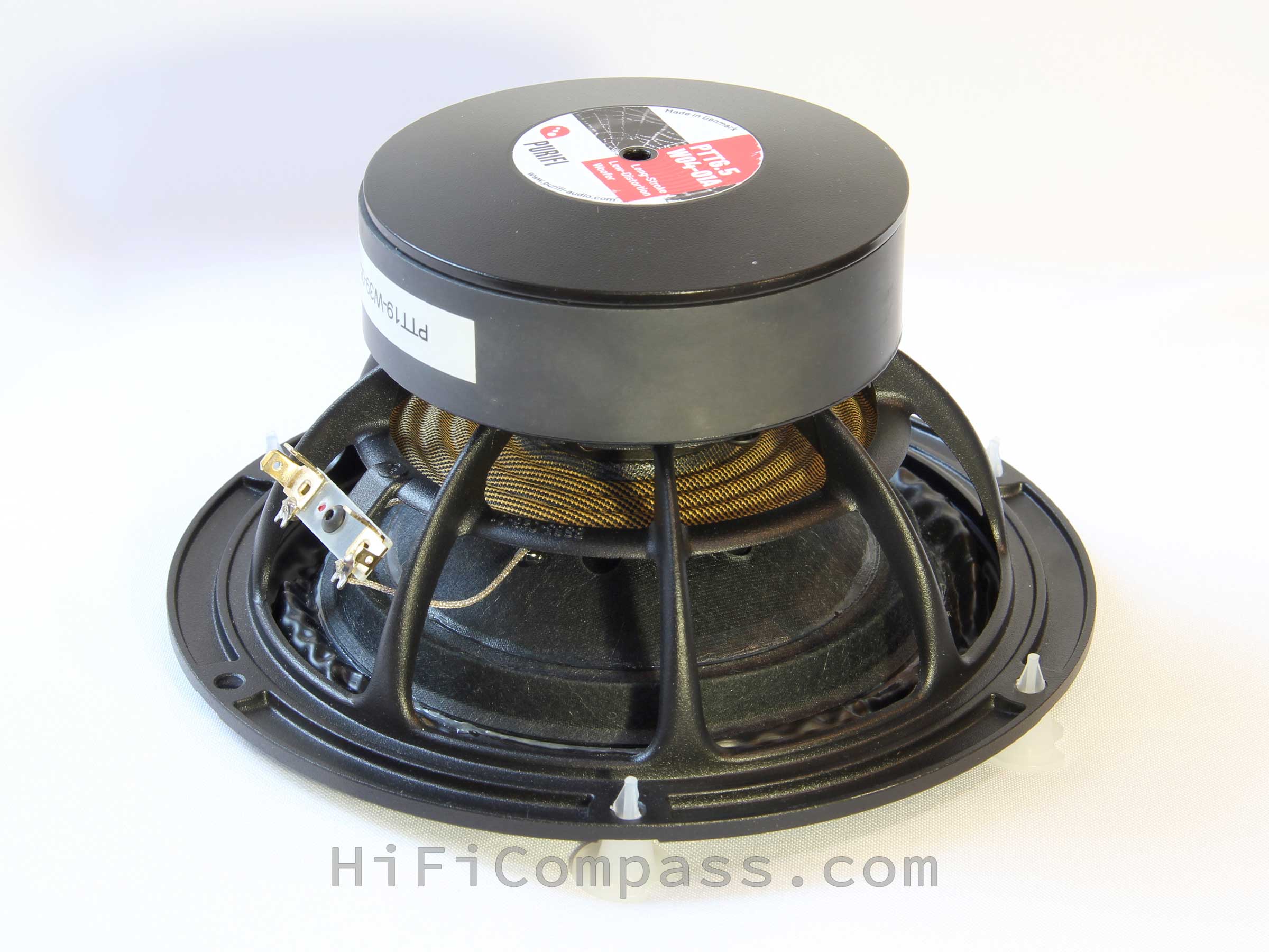
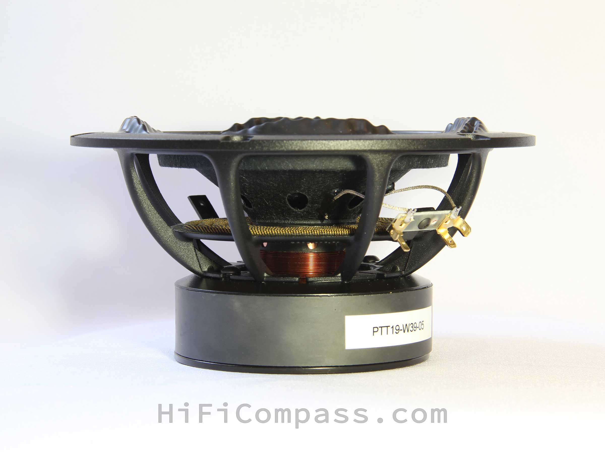
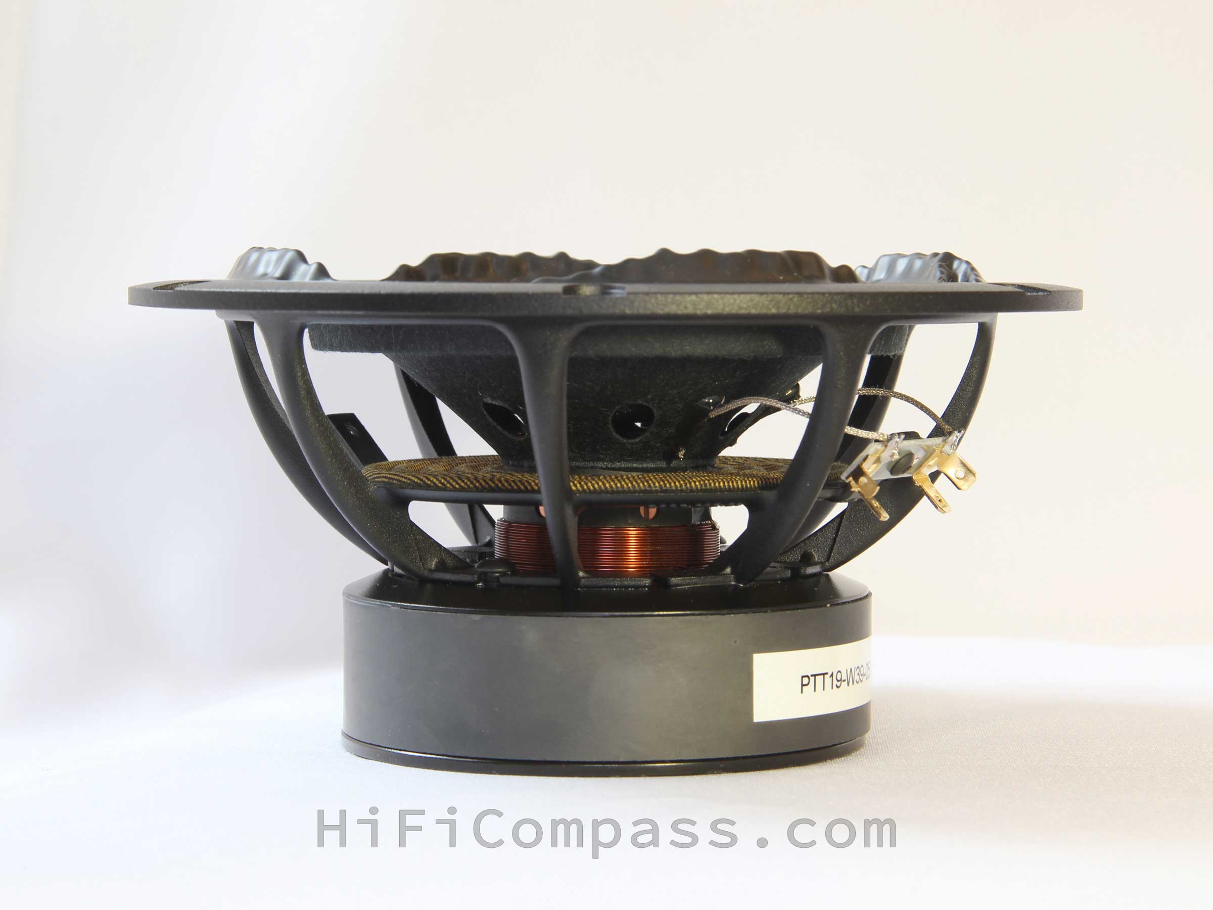
- The basket - is diecast from aluminum alloy with black microtextural powder coating. Acoustically very transparent. It is fixed to the magnet system by glue and two screws. I got the impression that the basket flange is a little flimsy, it could have been thicker. The flange is not solid in thickness, but profiled. Some companies do this. I hope that all reasonable mechanical loads were taken into account during development.
An interesting detail - the basket base, which is attached to the magnetic system, has a form not like a continuous ring, as in all other speakers, but has cuts between the ribs. What for? - The front and back plates of the magnetic system are made of steel and painted black to improve heat dissipation.
- The magnet is of ferrite, nothing special.
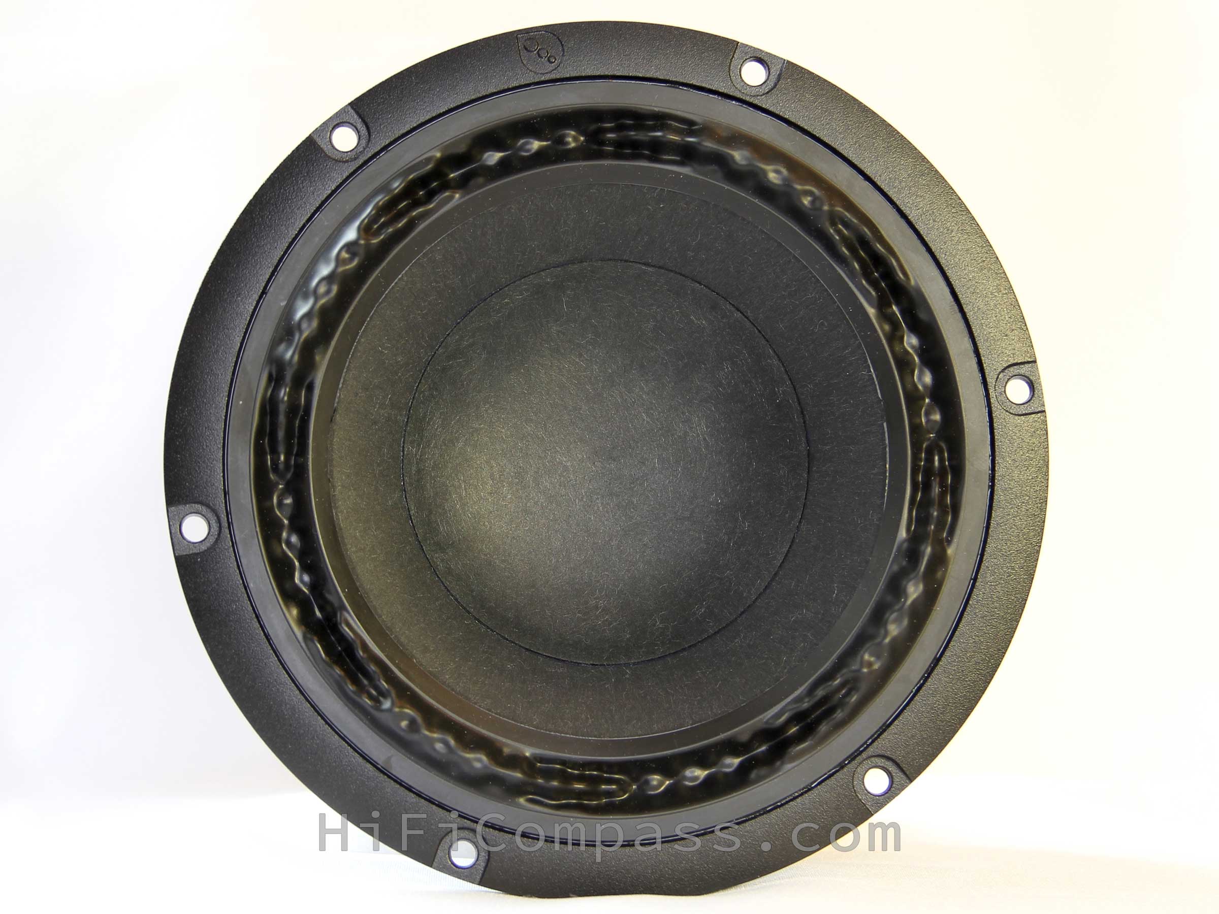
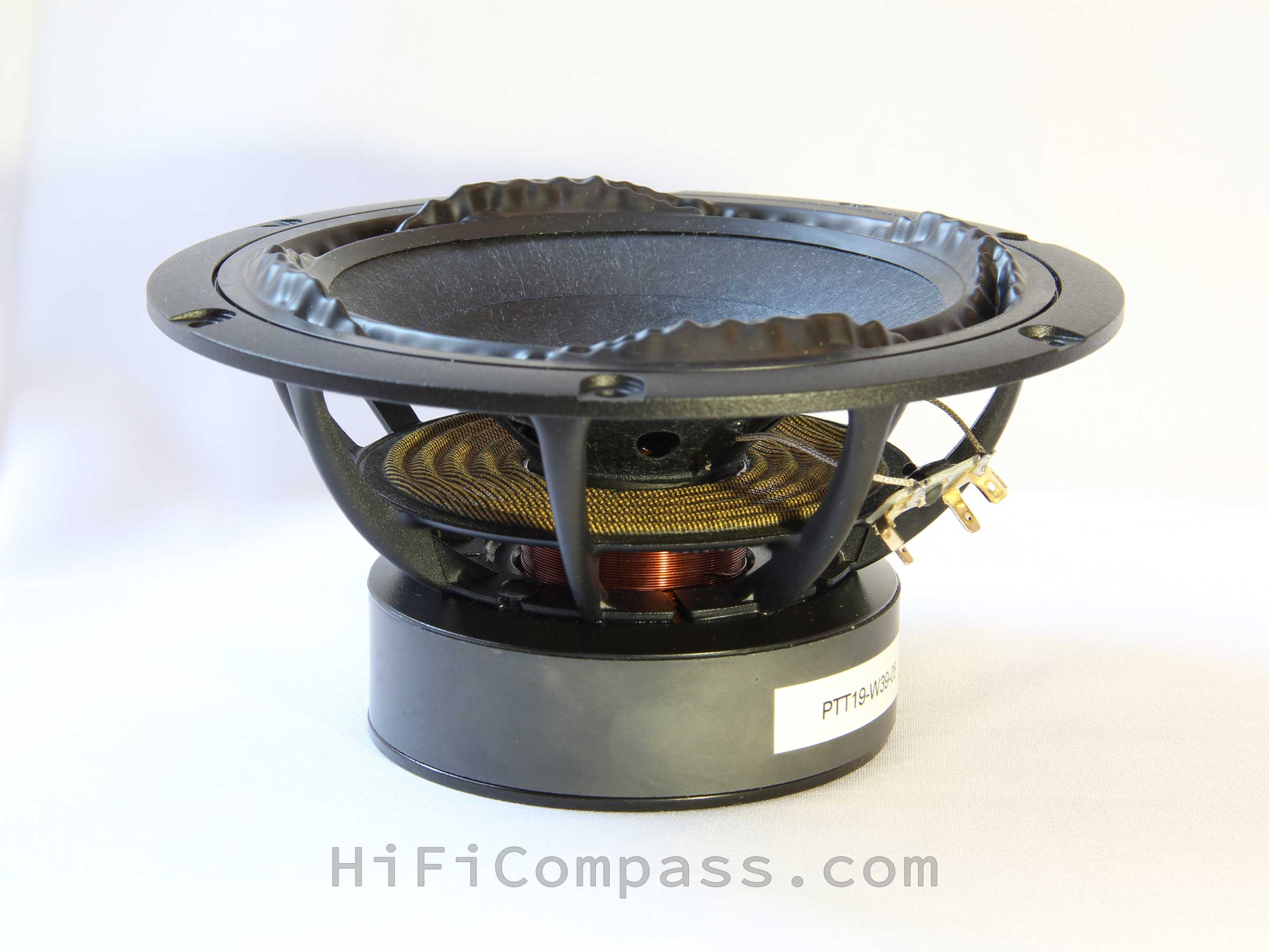
- The surround is very unusual. It is made of NBR rubber and in its shape resembles alternating mountain ridges. The four ridges look outward and another fours inward. The surround is absolutely symmetrical relative to the basket flange plane. This is the principle of PURIFI Neutral Surround - it is symmetrical, unlike conventional half-roll surround, due to which the effective radiation area remains constant throughout the entire voice coil excursion. In traditional half-roll surrounds the radiation area increases during the inward voice coile movement and decreases when moving outward, introducing additional nonlinearity. It's witty!
- The cone - is made of cellulose with addition of long synthetic reinforcing fibers. The cap is concave and made of the same material as the cone. The material is very tightly pressed and when tapped with a finger gives an echo, indicating a high stiffness of the membrane. The cone profile has a barely noticeable curvature, one can say almost straightforward. On the neck side the cone has six rather large openings for ventilation the space under the cap.
Another unusual detail is a stiffener with a triangular profile is glued along the entire circumference of the back side of the cone. Its made of the same material as the cone. This element significantly increases the cone stiffness and is designed to solve the eternal problem of suspension-edge-of-cone resonance. - The lead wires - silver plated, connected to a conventional terminal block on a fiberglass base. The stiffness of the terminal block and contacts could have been higher. You need to be careful when connecting the terminals.
- The spider is made of BIMAX material. BIMAX is featured by its durability and increased resistance to mechanical stress. As a rule, it is used in top models of speaker drivers.
- The voice coil former - is made of fiberglass. It is also a very popular non-conductive material, which allows to avoid additional losses from eddy currents, as in the case of aluminum formers, and to maintain high mechanical quality factor of the moving system. Through the vent holes in the former you can see a huge massive copper sleeve fitted on the central pole of magnetic system.
-
The voice coil is visually very long, overhang type, four-layer, wound with a copper-plated aluminum wire and ... and this can easily be seen - having a variable winding pitch. A very rare technique, so rare that I have not yet seen such a thing! Apparently, this is also one of the secrets of obtaining the linearity of BL (x) and Le (x).
Impedance frequency response
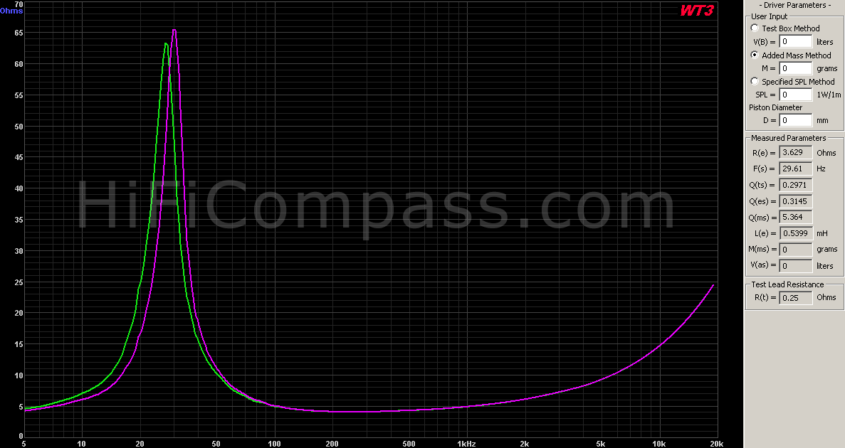
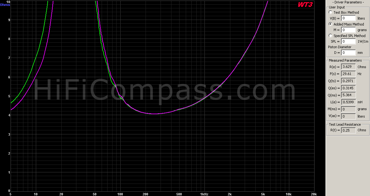
The diagrams show the impedance curves of the two midwoofers from a pair. The green curve - the speaker #4 after having been broken-in, the purple curve - the speaker #5 before broken-in. Before the speaker #4 had been broken-in, the curves completely coincided, which indicates the perfect selection of speakers in a pair.
The measured resonance frequency Fs = 29.61 Hz and Qts = 0.297 are slightly lower than the declared 30 Hz and 0.32 respectively. The difference is quite minor. More significant is the difference in the stated mechanical Q factor Qms = 8.3 and measured value of 5.364, which is reflected in the height of the resonance impedance peak - above 100 Ohms at the resonance in the datasheet and 65 Ohms measured. Most likely, the reason is a different value of mechanical losses.
Yevgeniy Kozhushko : Regarding Qms and the impedance peak. I use WT3 hardware to measure an impedance. It does a data acquisition quite correctly but I don't know which is speaker model it uses when calculating T/S parameters from collected data points. It is quite real that the model is old and doesn't take in account the last achievement in this field (FDD model, accounting of eddy currents and Re instead Rdc e.t.c). Maybe WT3 does sweeping too fast...
Lars Risbo : I might have the explanation for the higher Zmax we measure: we measure with a broad band noise like signal that is EQ’ed so that there is a lower voltage at low frequencies. This means that the coil excursion is very low. We have observed many times that the Zmax drops for most speakers when using a sine sweep or even worse if you sit with a tone generator searching for the max. Then all the energy is concentrated at the resonance and much more excursion is the result. The internal damping of rubber goes up with the excursion amplitude so the sine sweep method will show a lower Zmax than for the wide band noise. I am almost certain that this is the reason for the difference. Hard to argue which method is the most correct (no industry standard) but at least it is important to know the differences when comparing results.
Well, now is the most interesting part. The impedance curve is so smooth through the entire frequency range that it is impossible to believe in it. Without a single irregularities! No traces of breakups and this is just a fairy tale for a paper cone. I have never seen such a smooth curve in any midwoofer. Wow!
The impedance increasing at high frequencies is slightly higher than in speakers with two-layer coils and due to the higher inductance. This fact in itself does not matter much if it is possible to ensure the constancy of this inductance and impedance at any the cone position.
The impedance frequency response is a visiting card of a speaker and says a lot. In this case, it says about a moving system with low losses and a perfectly balanced cone a good motor. Excellent!
On-axis frequency response
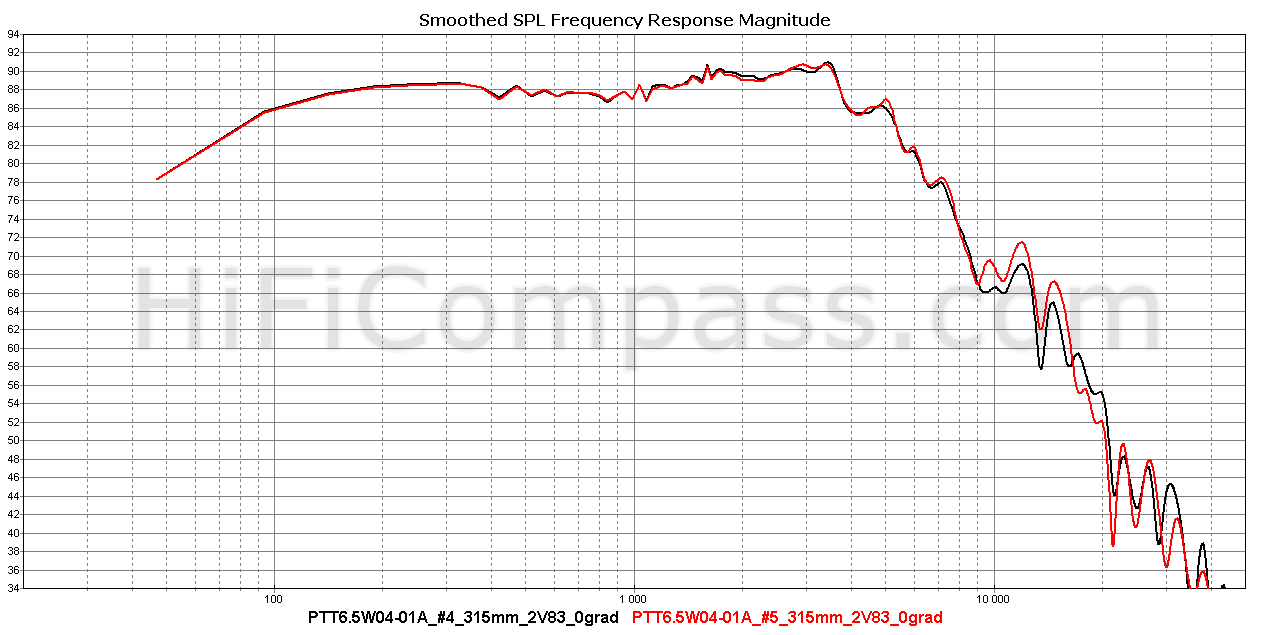
The frequency responses of the two samples perfectly match. The averaged measured sensitivity in the range from 300 Hz to 800 Hz is about 87.8 dB, which is 0.4 dB lower than the declared 88.2 dB. The discrepancy is very small and within the error limits of our measuring system.
In general, the frequency response is very smooth in the range up to 1.3 kHz (unevenness in the band 130 - 1300 Hz is no more than +/- 1 dB) with a small and smooth rising of 3 dB to a frequency of 3.3 kHz. Starting from 3.5 kHz, the frequency response begins to fall, almost monotonously, with a slope of about 20 dB/oct up to 40 kHz.
As you can see, there is no typical problem of edge resonance of the cone and surround in vicinity of the 1 kHz region and there are no signs of serious breakups.
In my opinion, it is just a great frequency response!
Off-axis frequency responses
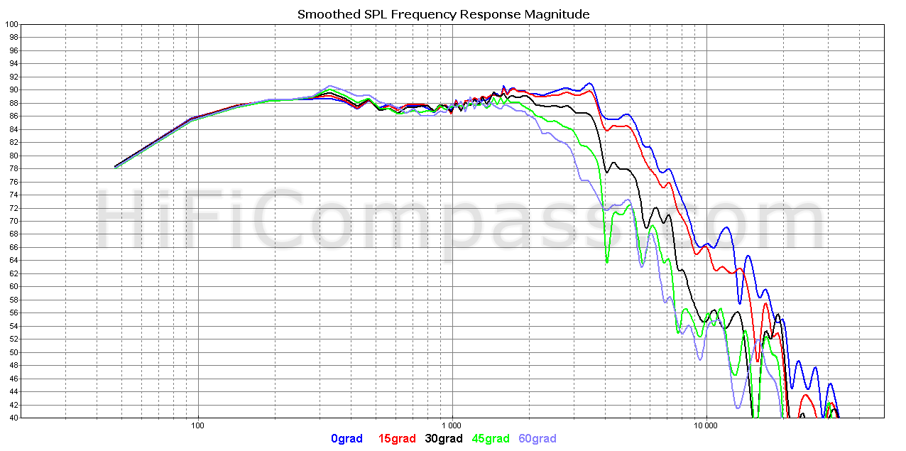
Off-axis frequency responses are just as good as axial frequency response, there’s nothing to add. No hidden resonances were found.
Harmonic distortion (315 mm)
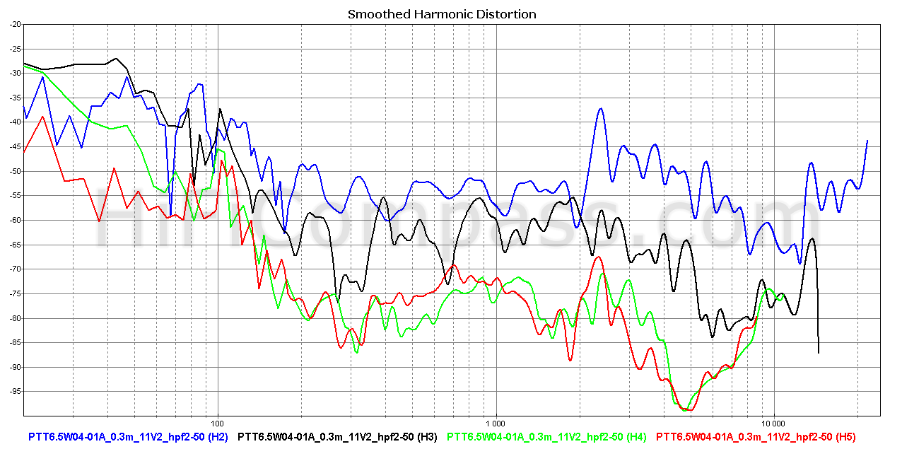
The harmonic distortion frequency responses at average sound pressure levels of 88 and 100 dB are given above. In these diagrams, we analyze the frequency range from 150 Hz and higher.
The distortions are very low, one of the lowest I encountered when testing 6" speakers. Particularly surprising is the low level of the second harmonic and the absence of problematic bursts of distortion in the 1 - 2 kHz range. Nevertheless, they managed to solve the problem of the suspension-edge-of-cone resonance. There is a slight burst of distortion in the 2.4 kHz region, but it is narrow and not so serious and most likely will not fall into the working frequency range of the speaker in a two-way system, and if it does, it will be weakened. There are also no signs of serious breakups even at high sound pressure levels.
The harmonic distortion measurements confirmed the values given in the datasheet. Fine!
Harmonic distortion (5mm - 20 mm)
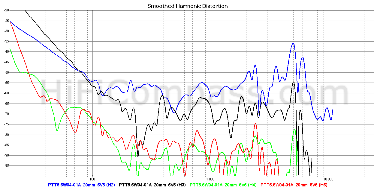
Due to the limitations of our measuring setup, it is more correct to use the results obtained in measurements in the near field at a distance of 5 to 20 mm from the cone when analyzing the nonlinear distortions of midwoofers in the frequency range up to 200 Hz. The diagram shows distortion at 5.6 volts. It is seen that below 80 Hz the harmonic distortion pattern is violated and the third harmonic begins to dominate. However, the overall harmonic level as for the 6" midwoofer can be described as "very low ". It is one of the best samples, which I have tested, regardless of the price. The lower limit of the frequency range, limited by distortion, can be considered as 30 Hz, which is very good.
Intermodulation distortion
The intermodulation distortion measurement is one way of analyzing device non-linearity. It is not an alternative, but an additional method and allows you to identify the spectral components of the inharmonious structure, which are much more harmful for high-quality sound reproduction and to which our hearing is more sensitive. It is believed that the measurement of harmonic distortion quite correctly reflects the degree of nonlinearity of the device and with an increase in their level, the intermodulation distortion also increases. Therefore, so far I have not measured the intermodulation distortion of the speakers, assuming that for a relative comparison of the speakers with each other a measurement of harmonic distortion is sufficient.
I was encouraged to reconsider my views, at first, the Bruno Putzeys article "Distortion, The Sound That Dare Not Speak Its Name", in which he very well describes the mechanism of the intermodulation distortion occurrence in a midwoofer, at second, an one interesting experiment that everyone can do. Its essence is the simultaneous supply of a musical signal to a midwoofer with a singing rather than speech (for better audibility of the effect), male or female vocals, or a violin, clarinet, flute, and sine signal with frequency of 30 Hz, the level of which can be adjusted. The sine signal causes a large cone excursion, which leads to the appearance of non-linearity of the suspension and the force factor. The suspension nonlinearity leads only to the appearance of harmonic distortions of the 30 Hz sine signal and does not affect the reproduction of midrange, while the modulation of the force factor leads to a change in the sensitivity of the speaker for midrange frequencies. This changing is manifested in the amplitude modulation of the voice notes with 30 Hz sine. Do such an experiment yourself and you will be very surprised at how much intermodulation distortion is heard and how they grow with an increase in the low-frequency component. Perhaps this will be a great discovery for you.
So, having tested in this way several very good midwoofers that I had in my hands, including ScanSpeak 18W/8531G00, Audiotechnology 18H521706SD-04, Satori MW16P-8, Satori MW19P-4, Usher 8945P and, of course, PURIFI PTT6.5W04 -01A, I was surprised how big the difference in sounding was. With the same low-frequency cone excursion the PTT6.5W04-01A sounded noticeably cleaner than the others.
This prompted me to include in my standard set of the measurements also the measurement of intermodulation distortion, as one of the methods that allow a deeper studying of the nonlinear behavior of devices.
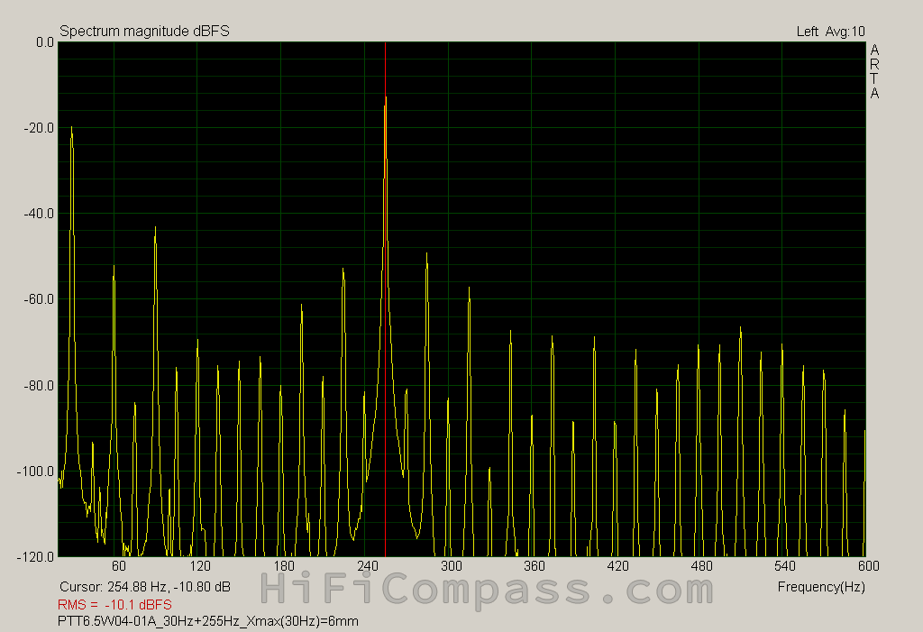
For testing I chose the frequencies of 30 Hz and 255 Hz. With this ratio (1: 8.5) the contribution of Doppler distortion is not yet dominant and the contribution of amplitude modulation can still be observed. In addition, this is a very realistic situation that occurs in both two-way and three-way systems. The measurements were performed for different 30 Hz cone excursions.
PURIFI PTT6.5W04-01A
%3D3mm_with_comments.png) |
 |
 |
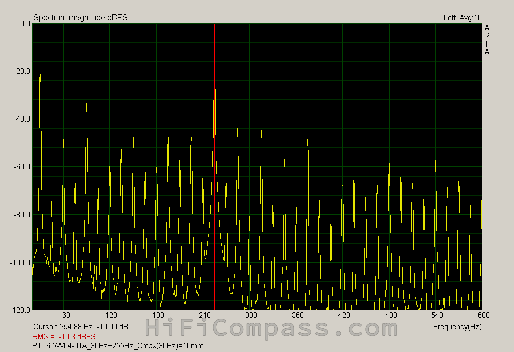 |
For the correct interpretation of the diagrams and estimation of the amount of intermodulation distortion it must be borne in mind that in addition to the intermodulation distortion, caused by the nonlinearity of the device, there is a fundamentally inevitable parallel mechanism associated with the Doppler effect and generating a spectrum of side components similar to the intermodulation distortion. The fundamental difference between the mechanisms is that the nonlinearity of the device leads to parasitic amplitude modulation (AM), and the Doppler effect to parasitic frequency modulation (FM). That is, the spectrum is a total result of two mechanisms. How then to distinguish them? It’s really difficult to distinguish, but to estimate the limiting values (r.m.s. value of the whole parasitic spectrum) of Doppler distortion you can use the formula recommended in the [G. L. Beers and H. Belar, ”Frequency-Modulation Distortion in Loudspeakers”, Proc. IRE 31, 132 (April 1943)]:
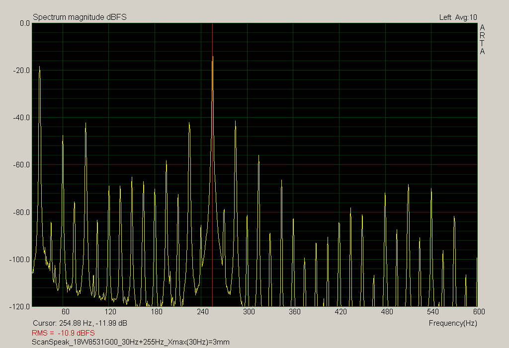
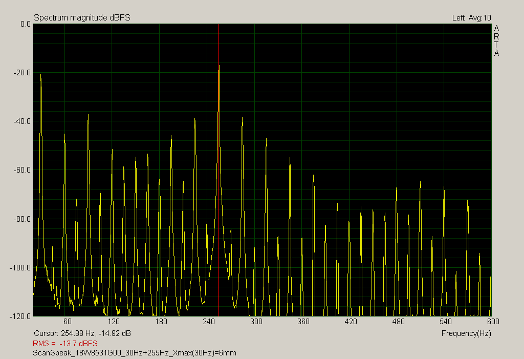
Below I give distortion spectrum obtained under identical conditions for some of the best midwoofers on the market. You can make your own conclusions:
ScanSpeak 18W/8531G00
 |
 |
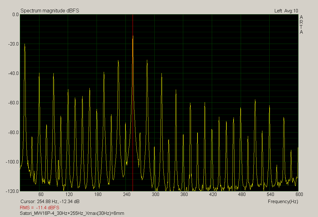
Satori MW16P-4
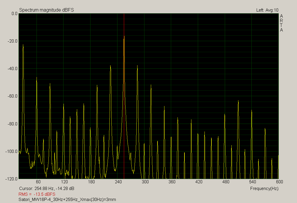 |
 |
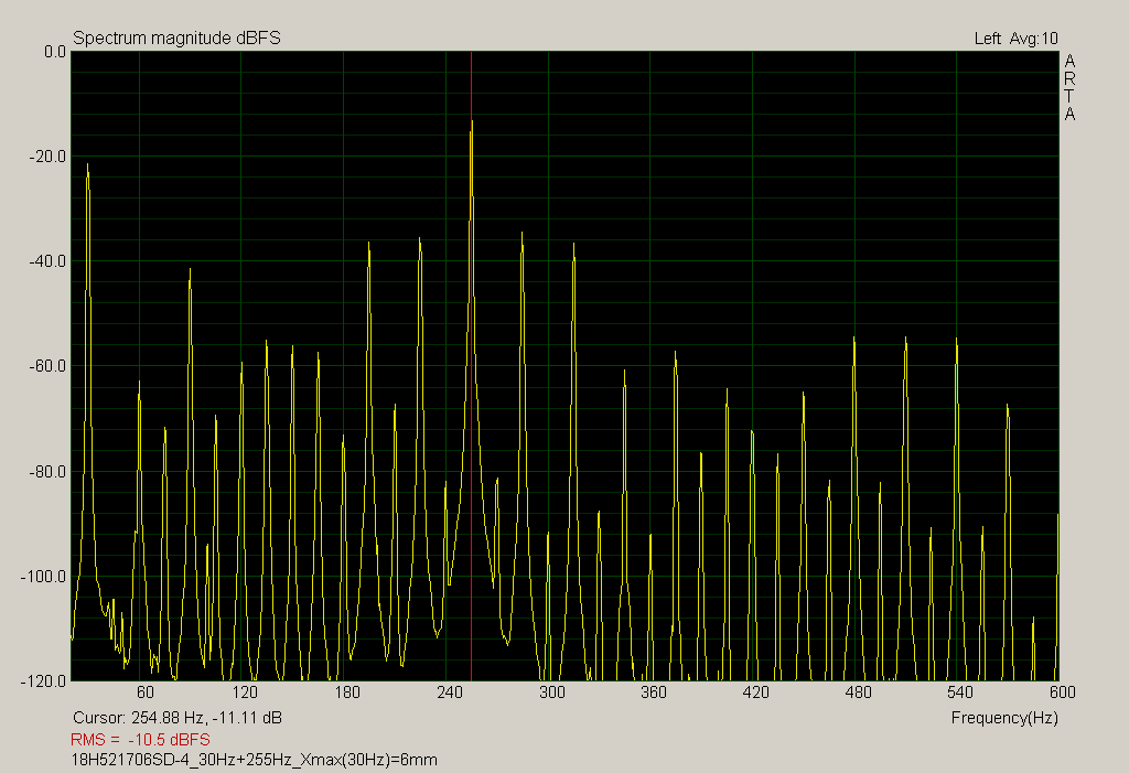
Audiotechnology 18H521706SD-4
 |
 |
Step response
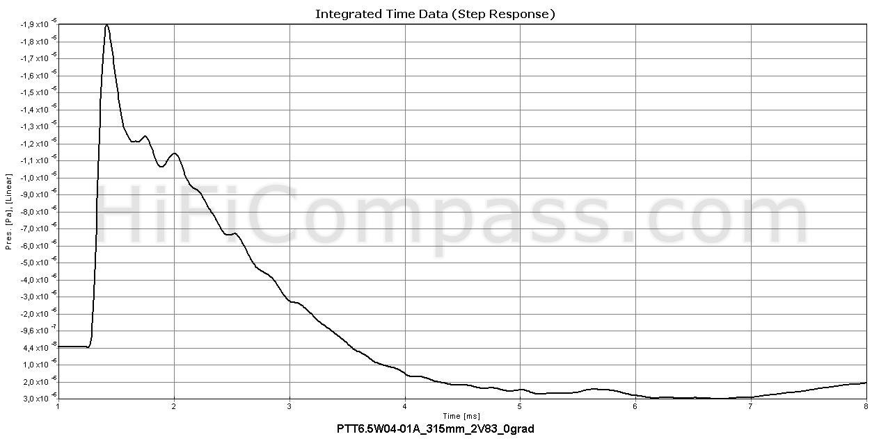
The step response shows excellent slew rate and fast falling. The returning to a start position is also monotonous. Small disturbances in the region of 1.8 ms correspond to approximately 3 kHz, where the frequency response begins to change its behavior from rising to falling. Apparently, there is a small resonance, which is difficult to recognize on the frequency response. Good transient response.
Waterfall
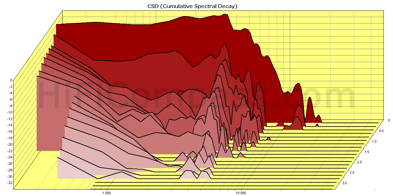
The waterfall shows the same effects as a step response, in addition exposing hidden resonances that are difficult to see in other types of measurements. In this case an echoes of resonance are observed near 3.5 kHz. The tail is not very long and already after about the time of 2.5 ms is reduced to a threshold of visibility.
Listening impressions
It is too early to speak about full-fledged subjective impressions, it's possible only after testing the midwoofer as part of a real loudspeaker. So far, I can only say about the impressions that I got while listening to the midwoofer in the measurement baffle during the measurement process.
The nature of the sound signature is very detailed and transparent. It seems to me that they are much closer in that to speakers with hard cones, but at the same time they do not lose the timbre shades so inherent for speakers with soft cones. At the same time, the distinctive softness and a kind of “veil” in the range above 800 Hz that can be heard from ScanSpeak 18W/8531G00 and other speakers from this family, or Usher 8948A, are completely absent. Very dynamic and contrast sounding. PTT6.5W04-01A has surprisingly low aerodynamic noise at an amplitude of 10 mm at a frequency of 30 Hz. Here they are quiet, unlike, for example, ScanSpeak Illuminator 18WU/4741T00.
The main purpose of the PTT6.5W04-01A is its using in highest-class compact two-way speaker systems. It can work up to 3 kHz. If we restrict ourselves to a lower frequency of the order of 30 Hz, then four of these midwoofers per side will do an excellent job even in open baffle designs.
However, the full potential of its huge linear stroke is not so simple to realize. As for vented designs, then due to the small area of the cone the speaker requires a small enclosure volume, from 7 to 15 liters, and a large air volume displacement requires an increased cross section of a port, so that the air speed in it does not exceed the permissible values. In turn, a large cross section of the port leads to its huge length while maintaining the same tuning frequency. As a result, the port length turns out not less than 400 mm and this is beyond all boundaries of good and evil.
A good way to overcome it - use a design with a passive radiator. There are no restrictions on this. Now, due to an existing trend in decreasing in loudspeaker dimensions, there are many options for suitable passive radiators on the market.
I have simulated several enclosure types for PTT6.5W04-01A using the VituixCAD program (by the way, a great program, I recommend it to everyone!). The first two six-pack diagrams are simulation results for a bass reflex type of enclosure. They are more likely theoretical in nature, since the port length for a 7-liter enclosure turned out to be 550 mm, and for a 13.4-liter one - 350 mm. For correct the midwoofer functionality in a volume of 13.4 liters an additional resistance of an order of 1 Ohm is required.
The second two six-pack diagrams are for a passive radiator and have real practical interest. In an enclosure volume of 10 liters it turns out to achieve F-3 = 46.2 Hz with a maximum sound pressure at 30 Hz of the order of 95 dB. And for a volume of 15 liters and an additional resistance of 1 Ohm we get F-3 = 35.6 Hz with a maximum sound pressure at 30 Hz of an order of 96.5 dB.
PTT6.5W04-01A in a bass reflex design
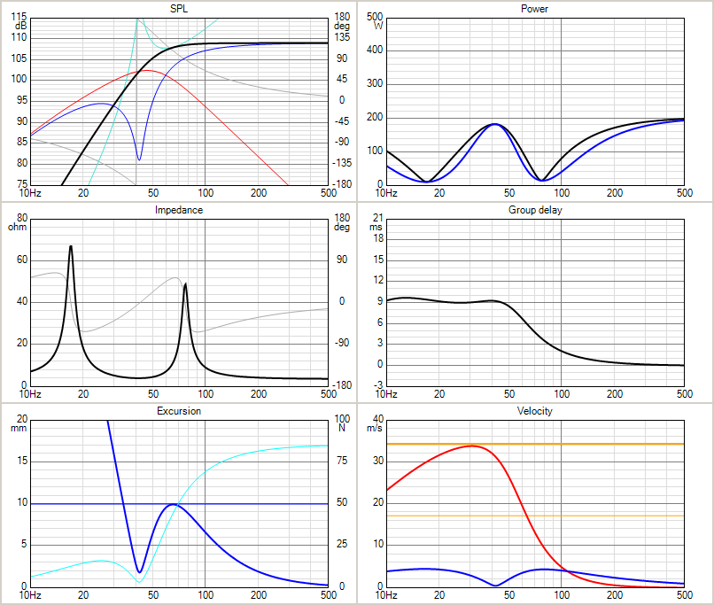 Bass reflex type of enclosure. Vb=7 liters, Fb=41.8 Hz, F3=55 Hz, Rg=0 Bass reflex type of enclosure. Vb=7 liters, Fb=41.8 Hz, F3=55 Hz, Rg=0 |
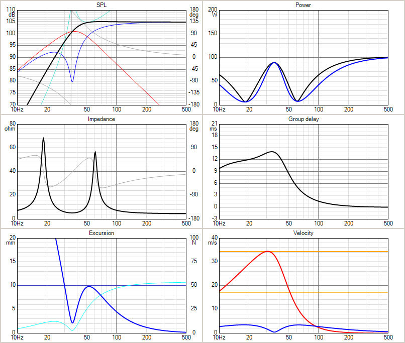 Bass reflex type of enclosure. Vb=13.4 liters, Fb=35.8 Hz, F3=38.3 Hz, Rg=1 Ohm Bass reflex type of enclosure. Vb=13.4 liters, Fb=35.8 Hz, F3=38.3 Hz, Rg=1 Ohm |
PTT6.5W04-01A in a passive radiator design
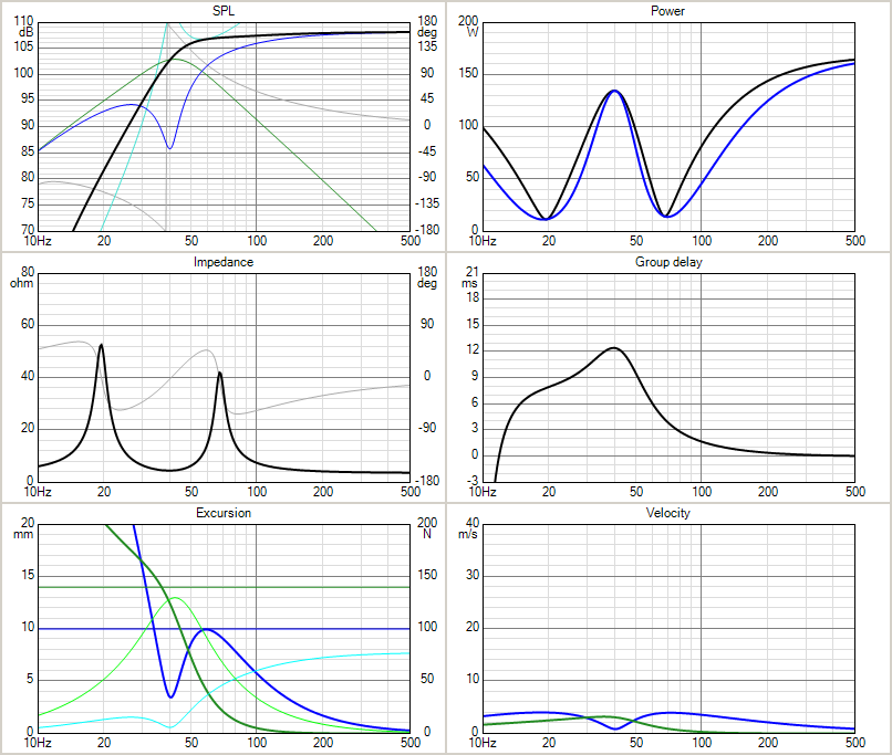 Passive Radiator type of enclosure. Vb=10 liters, Fb=40.2 Hz, F3=46.2 Hz, Rg=0 Passive Radiator type of enclosure. Vb=10 liters, Fb=40.2 Hz, F3=46.2 Hz, Rg=0 |
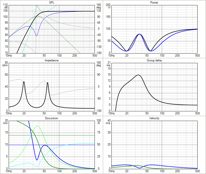 Passive Radiator type of enclosure. Vb=15 liters, Fb=35.6 Hz, F3=37.8 Hz, Rg=1 Ohm Passive Radiator type of enclosure. Vb=15 liters, Fb=35.6 Hz, F3=37.8 Hz, Rg=1 Ohm |
What is the price and where to purchase it?
As of the beginning of November 2019 the PTT6.5W04-01A midwoofers are just getting ready for sale. PURIFI company plans to launch an online store where it will be selling its products.
Regarding the price:
Lars Risbo: We are working hard on getting the web shop operating - hopefully within a few weeks. This is mostly for DIY'ers.
Currenty, the planned prices are:DIY pricing:
$390 @ 1-2
$334 @ 3-4
$279 @ 5-6
$230 @ 7-9
+VAT (depending on country)OEM prices are on quotation
Summary
Testing confirmed a very close correspondence of all the measured parameters to the declared ones with the exception of the mechanical quality factor Qms. It turned out a bit lower than stated, but this is absolutely not critical. Also the validity of the manufacturer's statements about technical achievements implemented in the midwoofer is confirmed. They really cracked a "long-stroke" code!
The measured characteristics of PTT6.5W04-01A attribute it to the highest caste of 6 "midwoofers. Many characteristics are at or above the best competitors currently on the market. Some characteristics (intermodulation distortion, frequency response of the impedance) are simply amazing. Honestly, this is the third speaker over the past two years, along with the BlieSMa T34A and Viawave SRT-7, which delighted and surprised me. These products push the progress ahead!
This is undoubtedly a great start for a young company and one of the best midwoofers in its class. Bravo, PURIFI !
I wonder if their first speaker is so good, then what is their first 1ET400A amplifier?
So, here is what I can highlight in the PURIFI PTT6.5W04-01A midwoofer:
- Modest sensitivity - 88.2 dB/2.83 Volt*1 m
- Huge linear voice coil excursion - real 10 mm per one direction
- Really working PURIFI Neutral Surround technology
- Hard cellulose based fibers filled cone having no any serious breakups
- Very even sound pressure frequency response
- Very low harmonic distortion
- Very low motor air noise at low frequencies
- Excellent intermodulation distortion
- Very good craftmanship
- Excellent impedance frequency response
- Can be used in 2-way loudspeaker up to the 3 kHz crossover point
- Except the high mass of the moving system (26.8 grams) there is nothing more to complain about
You can get more information about the measurement results here.
Yevgeniy Kozhushko/14.11.2019
P.S.
I would like to give an excerpt from a conversation with Lars Risbo, one of the co-owners and developers of PURIFI Transducer Technology, which affects the design and technical aspects of the new midwoofer:
Yevgeniy Kozhushko: Lars, what does the logo of Purifi brand mean?
Lars Risbo: Three droplets, being gradually purified down. As sketched by Bruno, the leaf initially pointed the other way, forming a P. Then a real graphics designer intervened.
The name itself is Putzeys-Risbo-Fidelity.
Yevgeniy Kozhushko: I was very glad to see paper as a cone material in the PTT6.5W04-01A. I like paper membranes because their natural timbre, smooth and rich sounding. The PTT speakers sound exceptionally well. I would characterize them as very dynamic, clear, transparent and natural sounding speakers.
Lars Risbo: Great to hear that you like paper - we all love paper as cone material here - its an amazing material. Carsten Tingaard has build up so much experience in selecting fiber mixes and fiber lengths. Unfortunately, there seems to some folks who consider paper as less good simply because it also happens to be quite cheap. There is not much appreciation for how much optimization of the geometry means for the performance - exotic materials seems to be a more sexy story. We have a client who insisted on an alu cone and the prototype has actually more distortion than the paper cone (plus a more peaky response). We are of course keeping an eye open for new cone materials we plan to continuously experiment. But good point you made about our documentation not mentioning paper.
Our marketing challenge is that only few people seem to care about measured performance and often judge quality just on the looks and materials. Our driver has all the expensive parts (except the special surround) hidden inside the motor but it looks quite normal seen from the outside and then its even using paper as cone material. There are also people who dismiss our driver due to its approx. 26 g Mms and 4 layer coil because they think it is 'slow' - that changes of course when they measure or listen to it. Our motor construction and use of very thick copper rings gets inductance down below a normal 2 layer coil so the bandwidth is not affected. Actually, a higher cone mass can allow a stiffer construction so higher mass can actually give higher bandwidth (at the expense of sensitivity).
Yevgeniy Kozhushko: The membrane is made of paper composite with some synthetic long fibers added?
Lars Risbo: It's a mix of cellulose with some other fibres and then hard pressed. The actual material of the fibres is part of the "secret sauce" but the precise mix of fibre lengths even more so. Coupled with an optimised profile this yields breakup behaviour that we think is rather more useful than, say, a metal cone.
Yevgeniy Kozhushko: I think the peripheral circular rib at the back edge of the cone is made for resolving surround-edge-of-cone resonance problem?
Lars Risbo: Yes, this is to strengthen the cone rim and thereby to suppress unwanted modes.
Yevgeniy Kozhushko: What materials are the basket and surround made of?
Lars Risbo: The basket is diecast aluminium, which tends to use recycled aluminium so the exact alloy varies a bit. To be honest, being able to use recycled rather than recyclable materials was a strong argument in favour of aluminium. The surround is made of NBR rubber so pretty much standard. Again, it is it's special geometry that makes the difference.
Yevgeniy Kozhushko: For what purpose is the base of the basket not made solid, but with slots between the spikes of the basket? I have not seen this anywhere before.
Lars Risbo: It wouldn't make much difference in any other speaker but when you manage to get such constant Le(x) it's worth considering even such minutiae as the shorting from eddy currents caused by the basket. The change in Le(x) is measurable for a solid base basket so we got this special basket designed and tooled.
Yevgeniy Kozhushko: What is kind of material the coil former is made of?
Lars Risbo: Glass fibre composite.
Yevgeniy Kozhushko: I see that the voice coil has variable winding pitch. Is it correct? I think it is one of the reasons of very linear BL(x) and L(x) behavior.
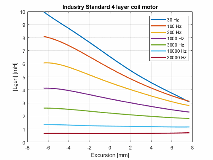
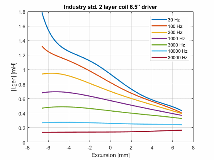
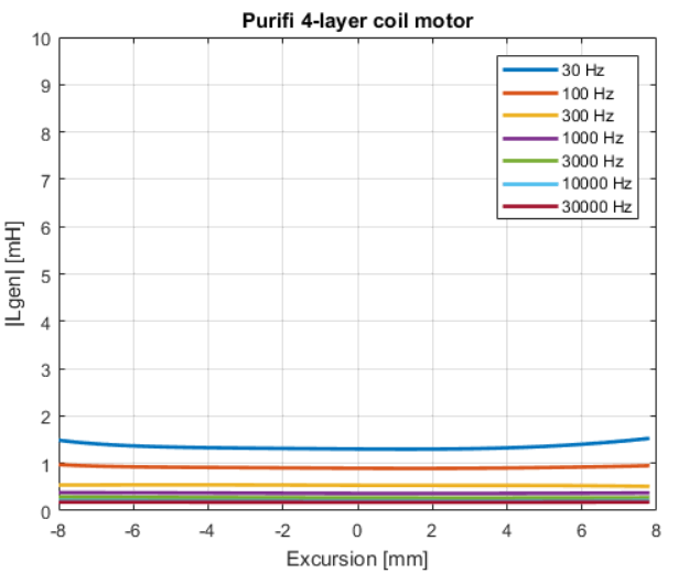
Lars Risbo: That's correct when it comes to BL(x), but it does very little to solve Le(x). That trick is hidden in the magnet system geometry. We'll discuss it when the secret outs but we should stress that we managed to flatten Le(x) down to DC. Shorting/Faraday rings aren't the secret for constant Le(x) because even the most solid Faraday rings won't help much below 100Hz. We use very thick and long copper rings (the by far most expensive components in the design) but this is mainly to control the hysteresis distortion from the iron and to reduce Le at mid frequencies.
Yevgeniy Kozhushko: Your speaker forced me to extended my of measurements and to add IMD ones because its are the measurements where PTT6.5W04-01A really excells. I have to add this type of measurements to my standart set and will be publishing them at individual speaker's measurement pages.
Lars Risbo: It is a great idea to include IMD plots since it probably tells a lot about more the sound quality. Whereas a 2nd harmonic might sound warm then there is nothing nice about the atonal IMD2 components coming from the very same2nd-order distortion source. I have done some two tone experiments and found that IMD products can be 20 or even 30dB lower than for a benchmark driver.
Our goal is indeed to drastically reduce the IMD and e.g. let bass and mids to come from the same driver. I suspect that a conventional half roll driver exhibits even more distortion/IMD when put in a small box due to the position dependent change of the radiating area Sd(x). This modulates the box air compliance - this does not happen in free air infinite baffle. So the improvements may be even bigger in a real life box.
Yevgeniy Kozhushko: I did a listening test - to a musical recording with female vocal I added 30 Hz sine signal and listened to a quality of midrange reproduction. PTT6.5W04-01A had undistorted sounding at much more 30 Hz excursions than many other renowned high quality speakers I have on hands. The PTT is able to find its place in the most sophisticated two way loudspeakers.
Lars Risbo: The two tone IMD is ultimately limited by the Doppler distortion (increasing proportionally with the voice tone frequency). The big question if of course how sensitive our human ears are to the Doppler distortion. The fact that we seem to hear a dramatic sound improvement with our new 6.5 Driver suggests that Doppler may not be so audible - more investigation is needed of course.
Yevgeniy Kozhushko:You mention in PTT6.5W04-01A specification about low magnetic hysteresis distortion...
Lars Risbo: We discovered that the magnetic hysteresis distortion is a problem both for speakers and class D amplifiers (when using a ferrite cored inductor). The same goes for cross over inductors with iron/ferrite cores.Yes it is a bit of a challenge to measure since it just shows up as odd harmonics when you drive a sine wave. For a more complex signal (like music) the memory effects get exposed (this most likely why it is so bad for the sound). Bruno did a simple experiment where the drivers response to a short tone burst changes depending on what the speaker played back a minute back in time - this change was in the order of 0.1%.
But even with a sine, we can see a telltale sign: if you plot harmonic distortion ratio for a sine versus level then you see a region where the HD ratio (both for the 3rd and 5th harmonic) increases slower or equal to 1st order. A memoryless 3rd order nonlinearity would show a 2nd order slope of this curve. This means that there is relatively more odd harmonics at low level from the hysteresis. You can also see it from the distortion vs frequency of the current when driving a voltage tot he speaker. The distortion is high at low frequencies (Kms and Bl etc) but as the frequency increases then the excursion drops very fast (2nd order with frequency). This means that the distortion drops very fast but then hits a minimum level and then rises with frequency again. This increase at high frequencies is due to the hysteresis (or rather magnetic domains flipping around). It increases in level with frequency since the induced voltage in the coil is proportional to the derivative of the flux in the coil. Our driver has its 3rd harmonic current distortion down around the -80dB level (there are graphs in the data sheet). We may in the future release improved models with even lower hysteric distortion - we have the technology but we are looking into how to manufacture it in volumes. The dynamics, staging, space and ‘black canvas’ are very much affected by this hysteresis distortion. Our driver is between 10 and 50dB better than what we have compared it to. Underhung drivers are prone to lots of hysteric distortion since there is so much iron around the coil.
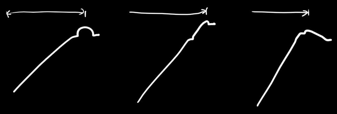
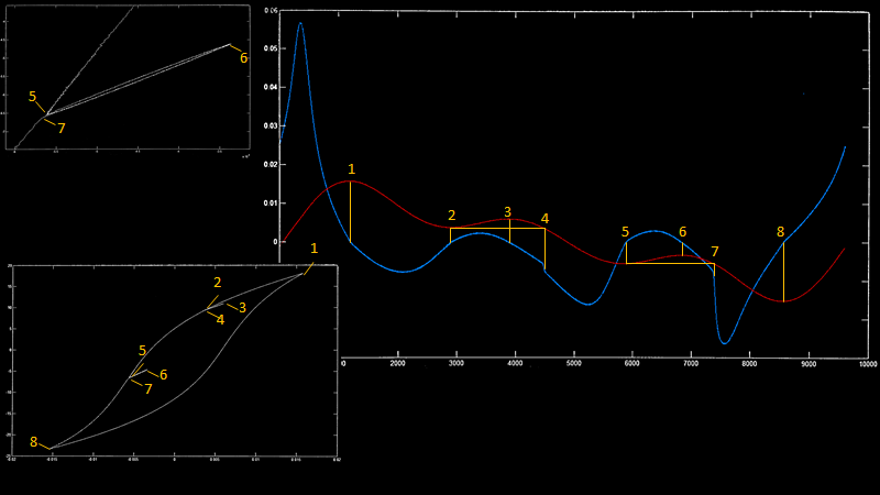
It was first when Bruno discovered the Preisach model that we understood how complex this distortion is. There are some animations of Preisach models on the web. Meanwhile, the slide from the presentation I sent you explains quite a bit (see the slide below). The plot is measured using two windings on a ferrite core. The first winding is driven by an amplifier and the voltage induced on the 2nd winding is recorded (blue trace) along the current in the primary winding (red trace). The white trace shows the traditional BH-hysteresis loop (the B field is found by integration of the induced voltage in the 2nd winding).
Normally you see the BH hysteresis loop for a sinewave with just one max and min current (H-field). Bruno got the idea to mix in a 3rd harmonic to the current so that we get more local minimums and maximums (points 1 2 3 5 6 and 8). The ferrite core remembers the minimum at point 2 and when the current swings up again towards a maximum at point 3 then the slope of the BH curve changes and we get a sub BH loop ending in point 4 where the current passes the prior minimum from point 2. At this point the BH curve shanges slope suddenly and we get a step in the induced voltage (blue). This voltage step is even bigger at point 7 when the current passes the past minimum at point 5. This voltage step is equivalent to a voltage step out of the amplifier and will be played back by the speaker. The ferrite will remember an infinity of past local maximum and minimum current and produce step voltages whenever these points are passed again. For a sinewave, we just get odd harmonics but for a complex music signal, we get an extremely annoying complex distortion that our ears are very sensitive to. Its not random noise (for which our ears are forgiving to) and it is also not a simple nonlinearity without memory. The response of the speaker depends on what it played moment ago (or even yesterday). When you reduce this distortion then our experience is that we get a much more dynamic sound. A transient passes all these remembered past maxima and minima so transients get very distorted compared to a steady sine wave.
For those who are interested in tracking the discussion about the midwoofer PTT6.5W04-01A - I invite you to visit a thread on the well-known resource audiosciencereview.com


CONTACTS
- Ukraine
- (+380) 95 904 7827
- hificompass@gmail.com
LAST NEWS
-
16 Jan 2024
-
08 Jan 2024
-
04 Jan 2024
-
17 Jan 2023

Comments (2)
Thanks for another interesting article, Yevgeniy. Looking forward to your test of the Purifi PTT4.0W04-01A as well. All the best for 2020!
Thank you! Wish to all to discover many new interesting and amazing speakers in New Year!