HiFiCompass
MatriXover-III - universal matrix three-way crossover
I want to tell you about the realization of my dream of many years - the creation of a universal three-way passive crossover MatriXover-III. This crossover turned out to be the most complicated, the most labor-intensive and the most expensive in my practice to date. The concept, design, circuit topology, components selection and physical realization took at least a year. MatriXover-III was a logical continuation of the two-way MatriXover-II project, although it was conceived long before it. It was decided to practice on a simpler project first, so MatriXover-II was born first, after which many ideas from it have successfully migrated to MatriXover-III.
The primary purposes of MatriXover-III:
- Facilitate, improve efficiency and speed up the development process of three-way loudspeakers
- To get the possibility of the most accurate adjustment of crossover parameters of the developed loudspeakers directly in the target listening room, taking into account the room acoustic properties, sound reproducing equipment and personal taste preferences of the customer
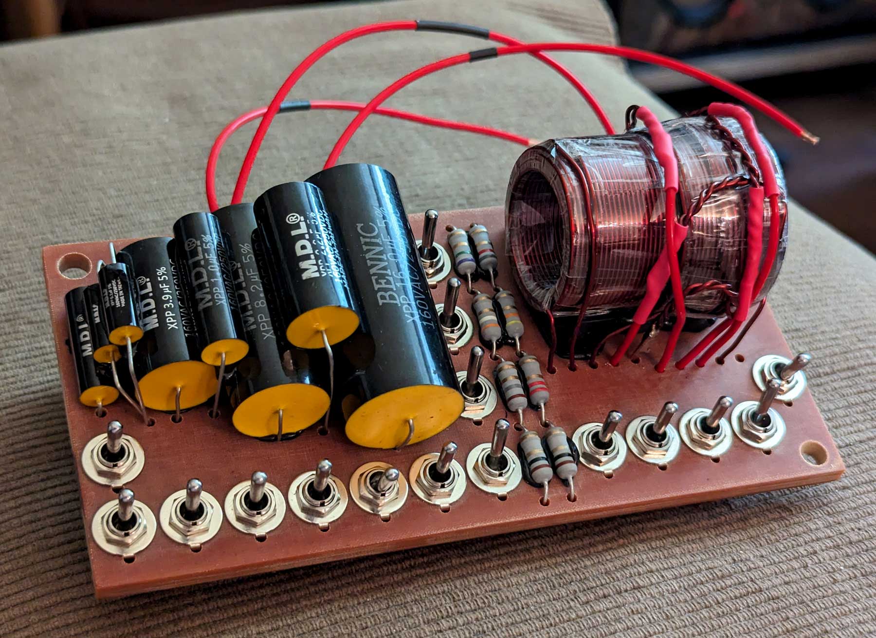
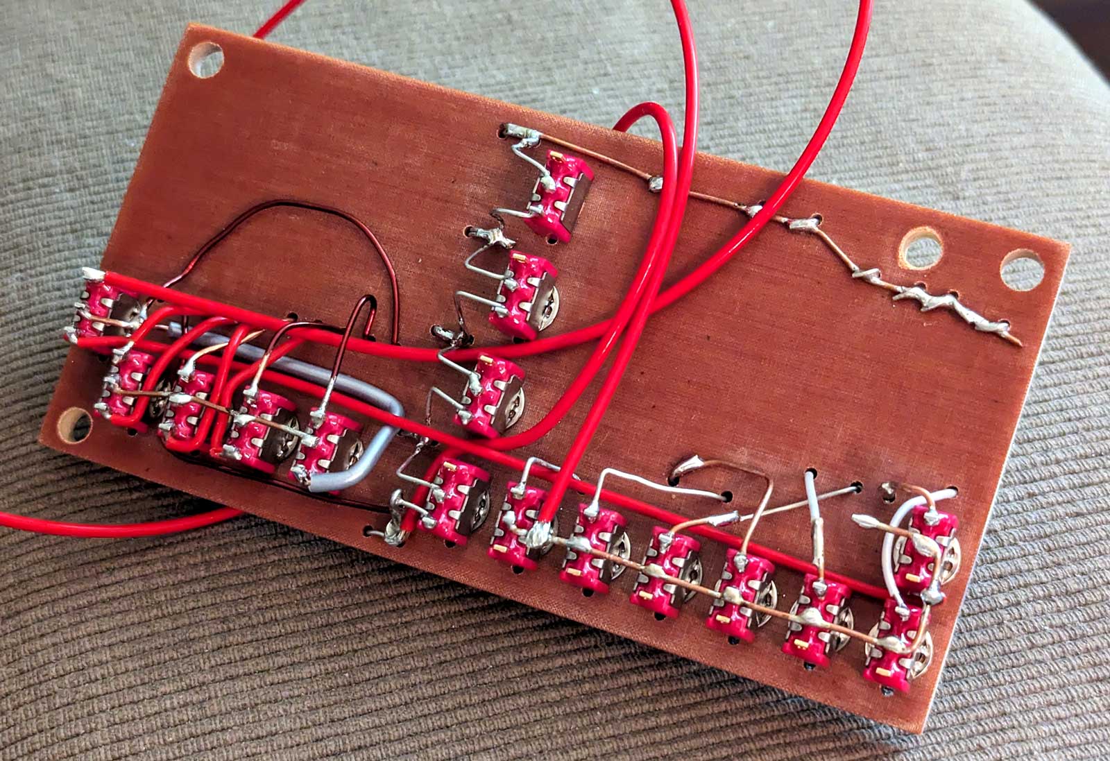
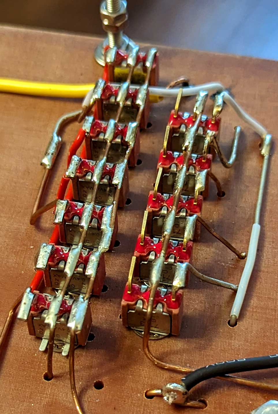
- To implement the ability to quickly and clearly compare (or demonstrate the difference) of the sound signature of different types (different manufacturers) of critically important crossover components. For this purpose the design provides toggle switches for quick switching and terminal blocks for connection of tested components
It is quite possible that for someone this project in the era of widespread use of digital crossovers with their fantastic capabilities will seem like complete nonsense and an unnecessary anachronism, but I have my own thoughts on this matter, and I hope that professional loudspeaker designers will be able to truly appreciate my efforts![]() .
.
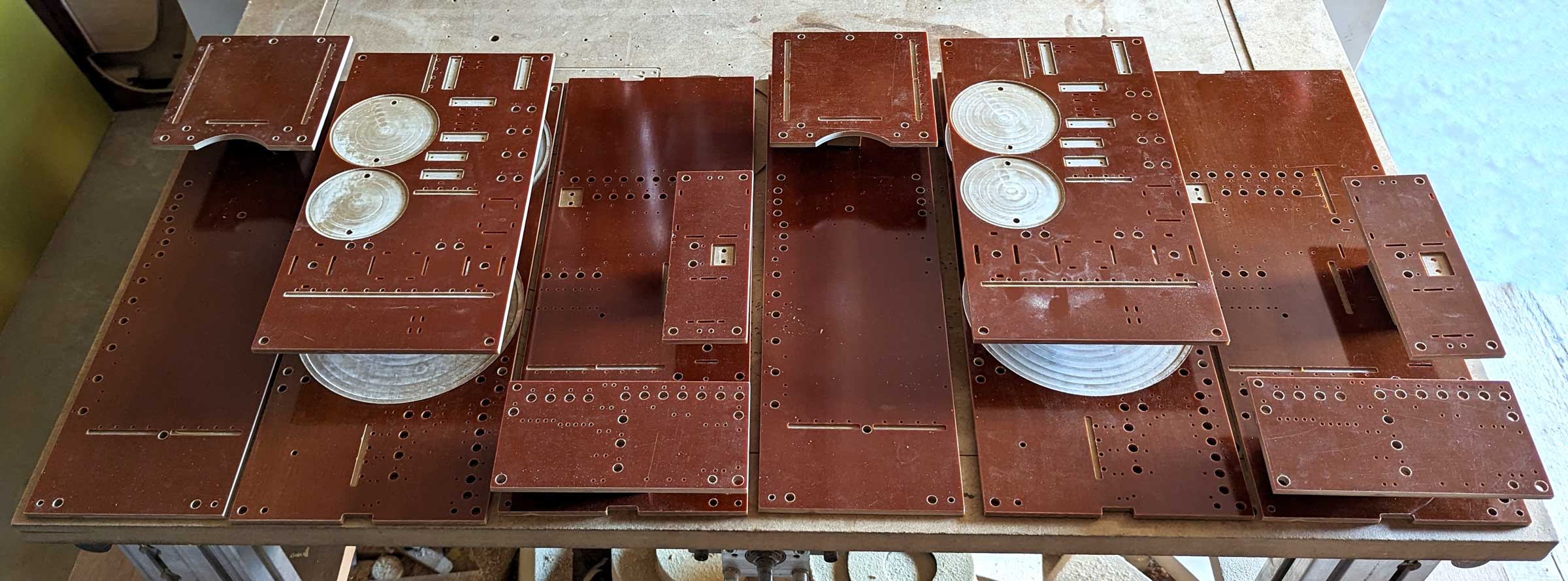
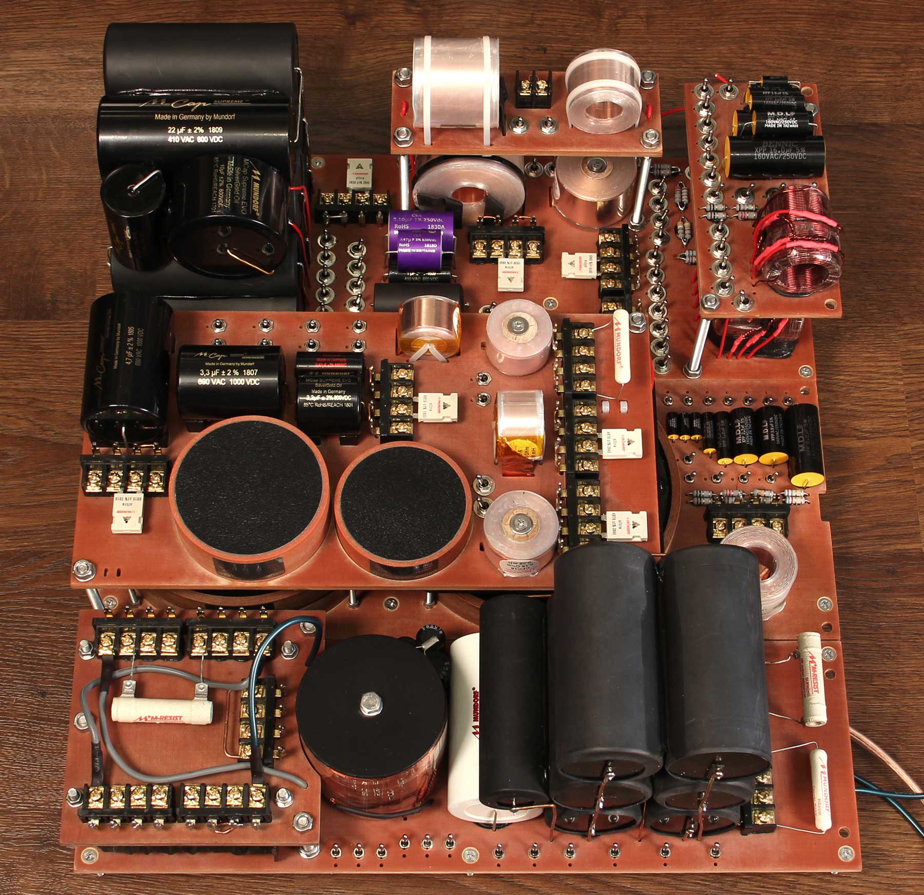
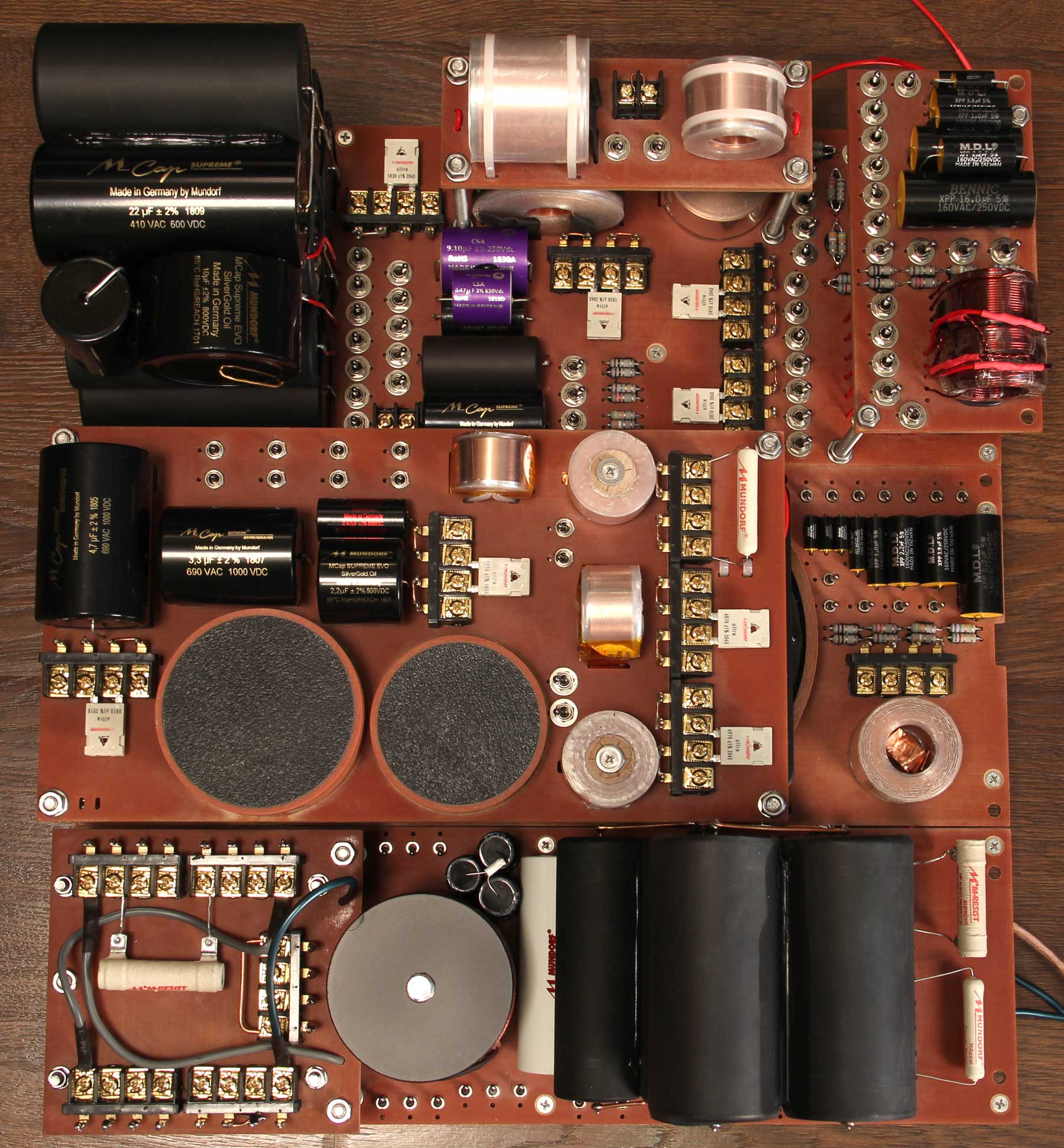
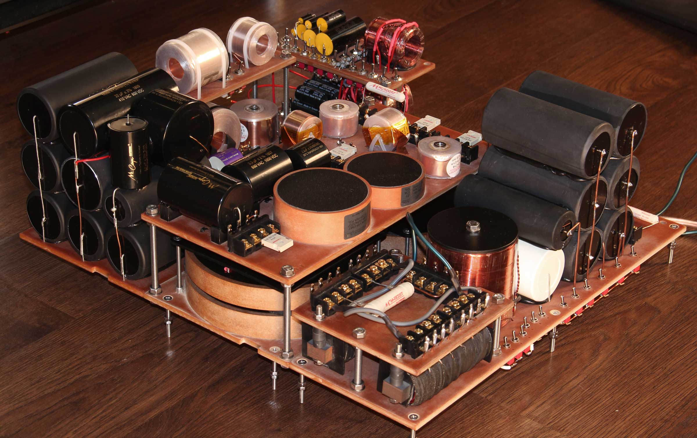
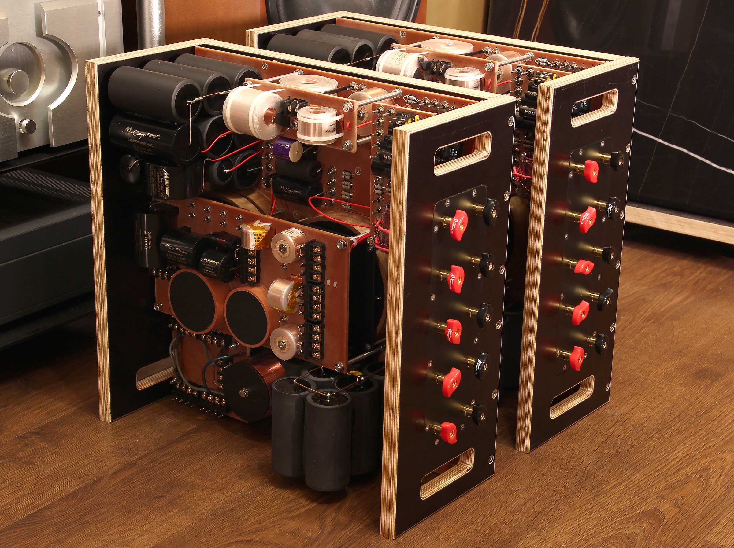
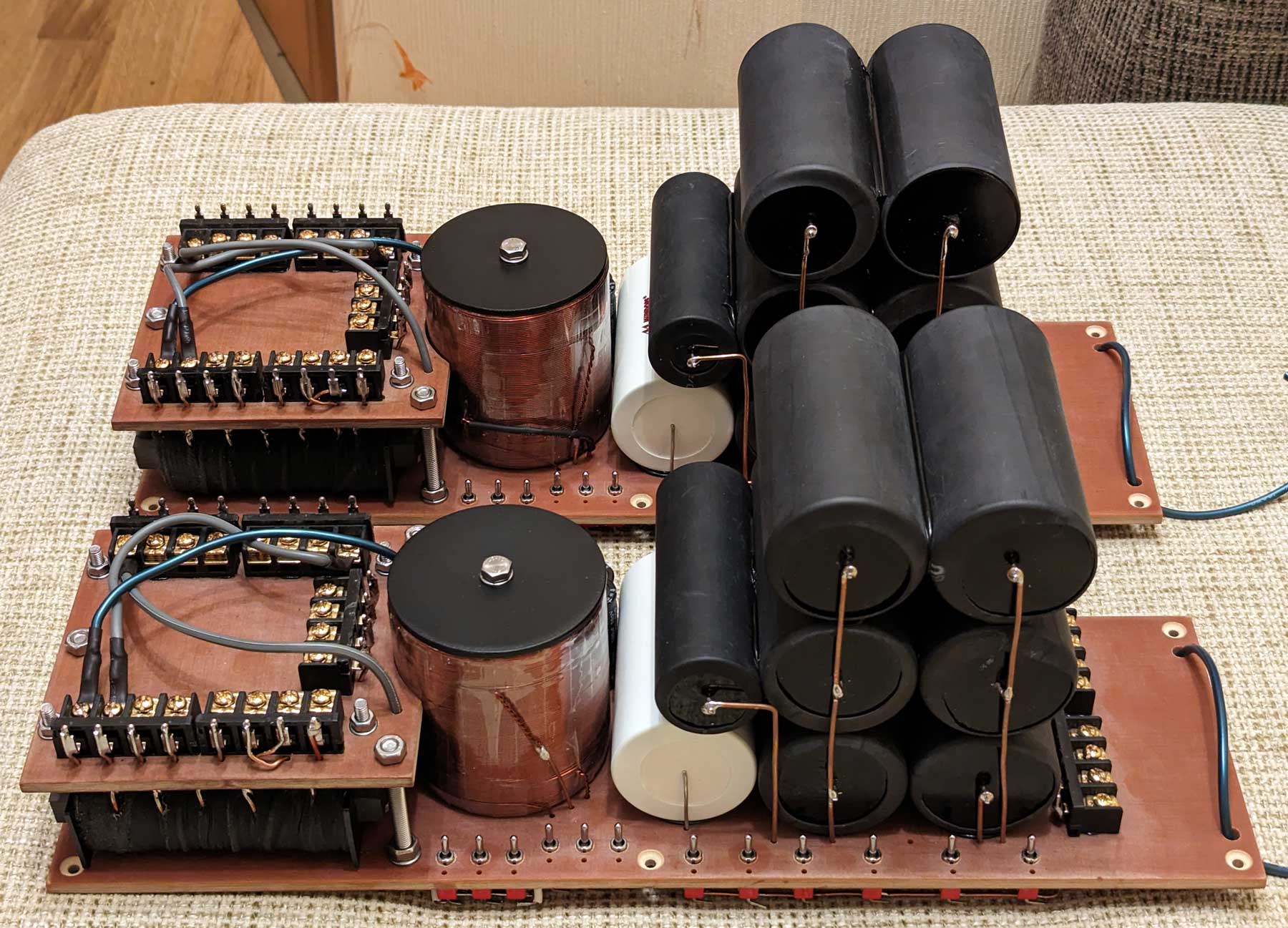
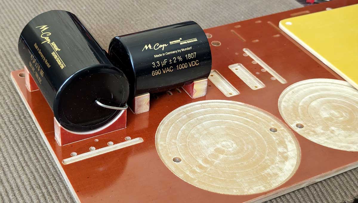
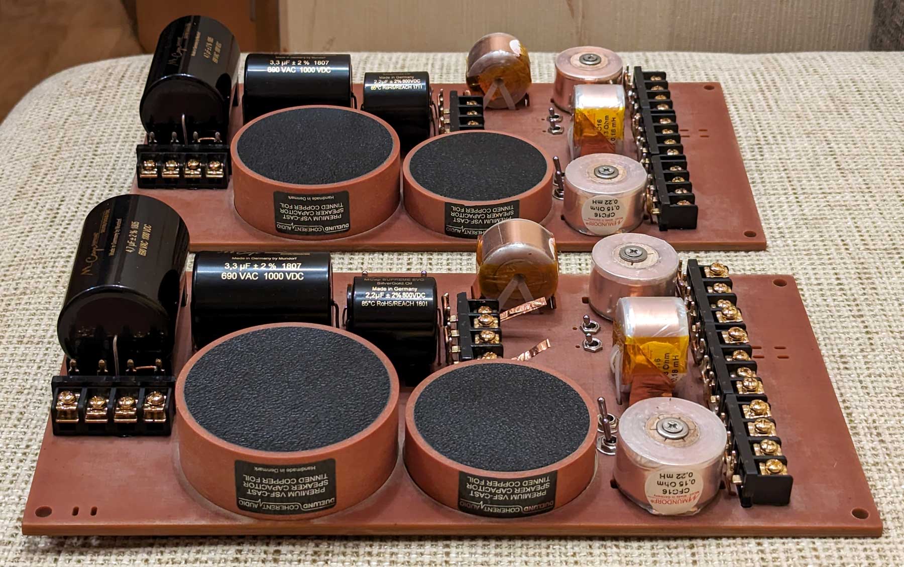
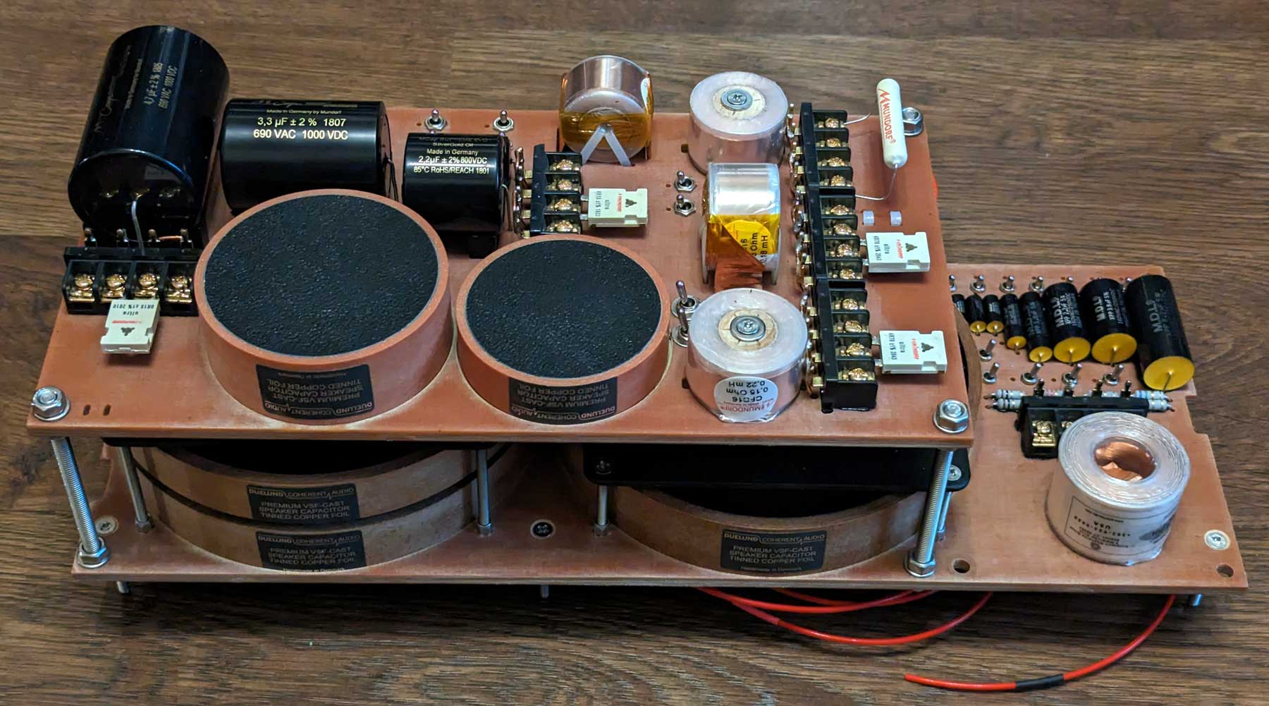
Structurally, MatriXover-III is made in the form of two portable units, which are U-shaped supporting frame made of 21 mm thick plywood, inside of which separate modules of low-, mid- and high-pass filters are installed. The filters modules have a two-story construction and are assembled on 14 boards made of CNC-milled cotton fiber/resin composite. Both vertical and horizontal working positions are possible.
Special attention during the development of the crossover was paid to minimizing the parasitic mutual influence of components on each other, namely:
- Reducing the parasitic mutual induction of adjacent inductance coils by optimizing their mutual orientation and spacing.
The technique was to use one coil as a transmitter of the magnetic field and the second coil as a receiver. The transmitting coil was supplied with a signal from an oscillator with frequencies of 100 Hz, 1 kHz and 10 kHz, and the position of the receiving coil was determined by the minimum response. The parasitic inductance variation was achieved to within 2% of the nominal value in the worst case. It means that the total value of inductance L∑ of two series-connected adjacent coils L1 and L2 was at the level (L1+L2)*0.98<L∑<(L1+L2)*1.02. Naturally, the new value after completion the assembling was reflected in the actual circuit diagram. It was possible to achieve even better results, but in this case it would not have been possible to fit into the planned overall dimensions of the product, so a reasonable compromise was chosen. - Reduction of parasitic influence of adjacent metallic elements, both para- and diamagnetic (screws, aluminum capacitor housings, large copper foil capacitors, large metal parts of terminal blocks) on coil inductance. This is achieved by selecting the optimum distance to the influencing elements and their material. For example, absolutely all screws and nuts are made of non-magnetic stainless steel. The parasitic inductance variation of less than 1% of the nominal value was achieved.Very often I see with a smile numerous crossovers of well-known brands on the Internet, which are full of design blunders. For example, inductance coils stand close to large capacitors in aluminum cases. In such cases, in the most unfavorable arrangement of components, you can easily get a dip in inductance value of up to minus 20%(!) at 10 kHz
 . Or a much more common case when the axes of closely located coils are rotated by 90 degrees, but are not in mutually perpendicular planes. If such coils belong to filters of adjacent bands, then already by just one photo of crossover you can determine the technical level of designers and their works.
All electrical connections are made using the following types of hook-up wires:
- SOCT-16: Neotech Solid Copper Wire (UPOCC in Teflon isolation)
- STDCT-16: Neotech Multistrand Copper Wire (UPOCC in Teflon isolation)
- SOCP-14: Neotech Multistrand Copper Wire (UPOCC in PVC isolation)
The external interface uses binding posts made of tellurium copper (Cu 99.5%) from the Propeller Post brand, which have proven themselves over many years.
The overall dimensions of the MatriXover-III are 460x470x200 mm. Weight - 22 kg. Heavy, damn it, but, thank God, still liftable![]() .
.
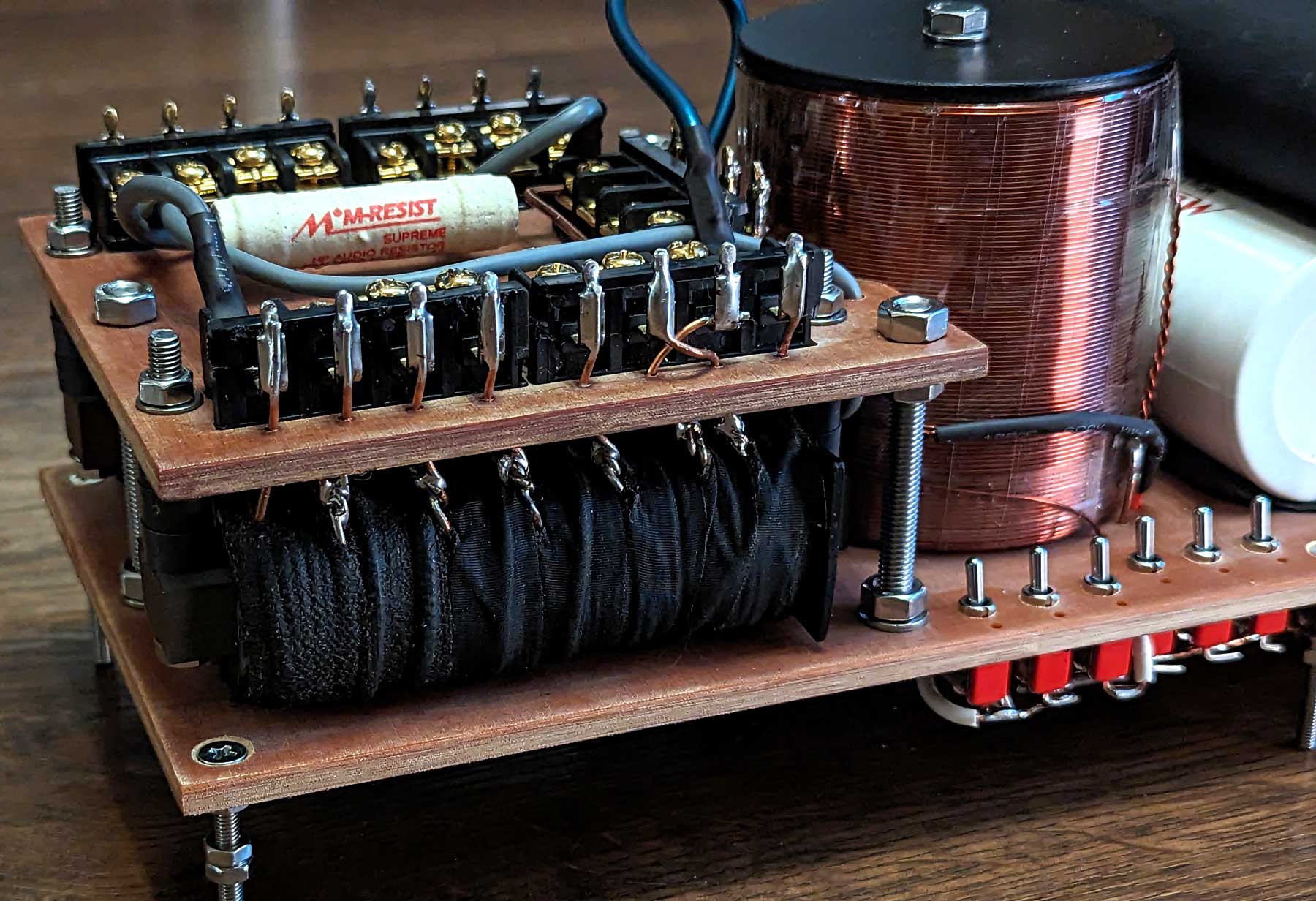
The low-pass filter module has the following features:
- Possibility of implementing electrical filters from 1st to 3rd order
- Two inductors with laminated steel cores and multiple taps allow you to get any series filter inductance in the range from 3 to 13 mH with a step of 0.3-0.5 mH
- Notch filter with air inductor with 35 mH, 43 mH and 50 mH taps
- Main filter capacity - choice of 64 values in the range from 5.1 to 300 µF
- Terminal blocks for additional resistors and inductors
- The main capacitors used in the filter are Mundorf Supreme 10 μF, 22 μF (x6), Mundorf EVO Oil 150 μF, MDL XPP250 5.1 μF
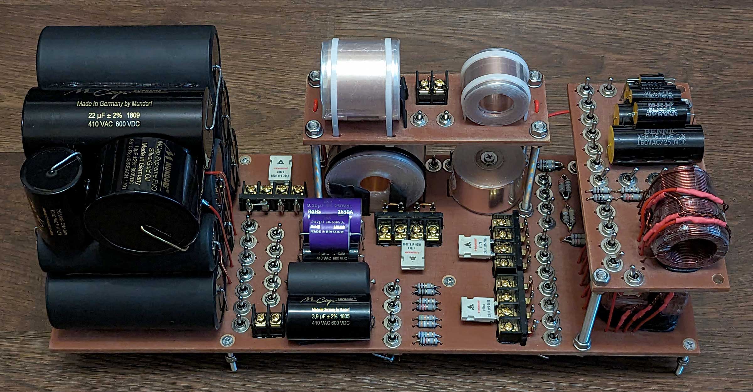
The mid-pass filter module has the following features:
- It is possible to realize electrical low-pass filters from 1st to 3rd order and high-pass filters from 1st to 2nd order. It is possible to connect a speaker bypassing the high-pass filter
- The main inductance coils are Goertz (USA) and Mundorf (Germany) copper foil coils. The inductance range is from 0.1 to 1.5 mH, plus the ability to connect an additional external inductance
- The serial capacitors used in the filter are Mundorf Supreme 4.7 μF, 10 μF, 22 μF (x7), Mundorf Supreme EVO Silver-Gold-Oil 10 μF, Duelund CAST Cu-Sn 6.8 μF (installed on the high-pass filter board)
- Adjustable parallel notch filter with tuning frequency from 42 to 410 Hz
- Adjustable parallel or series notch filter with tuning frequency from 890 Hz to 19 kHz
- Terminal blocks for additional resistors
The high-pass filter module has the following features:
- Possibility to realize electric high-pass filters from 1st to 3rd order
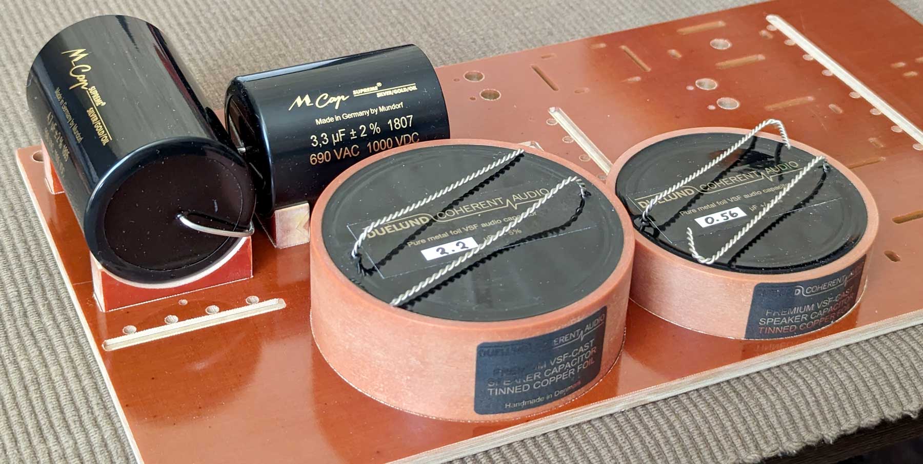
- The main capacitors used in the filter are Mundorf Supreme Silver-Gold-Oil 4.7 μF and 3.3 μF, Mundorf Supreme EVO Silver-Gold-Oil 2.2 μF, Mundorf Supreme 0.47 μF, Duelund CAST Cu-Sn 0.56 μF, 2.2 μF, 3.3 μF and 4.7 μF.
It is possible to select the type of capacitor - either only polypropylene, or only copper foil paper-in-oil, or a combination of both - Mundorf CFC16 (Germany) copper foil coils are used as the main parallel inductance coils. The inductance range is from 0.1 to 0.65 mH, plus the possibility of connecting an additional external inductance
- Adjustable parallel notch filter with tuning frequency from 600 Hz to 40 kHz
- Terminal blocks for additional resistors
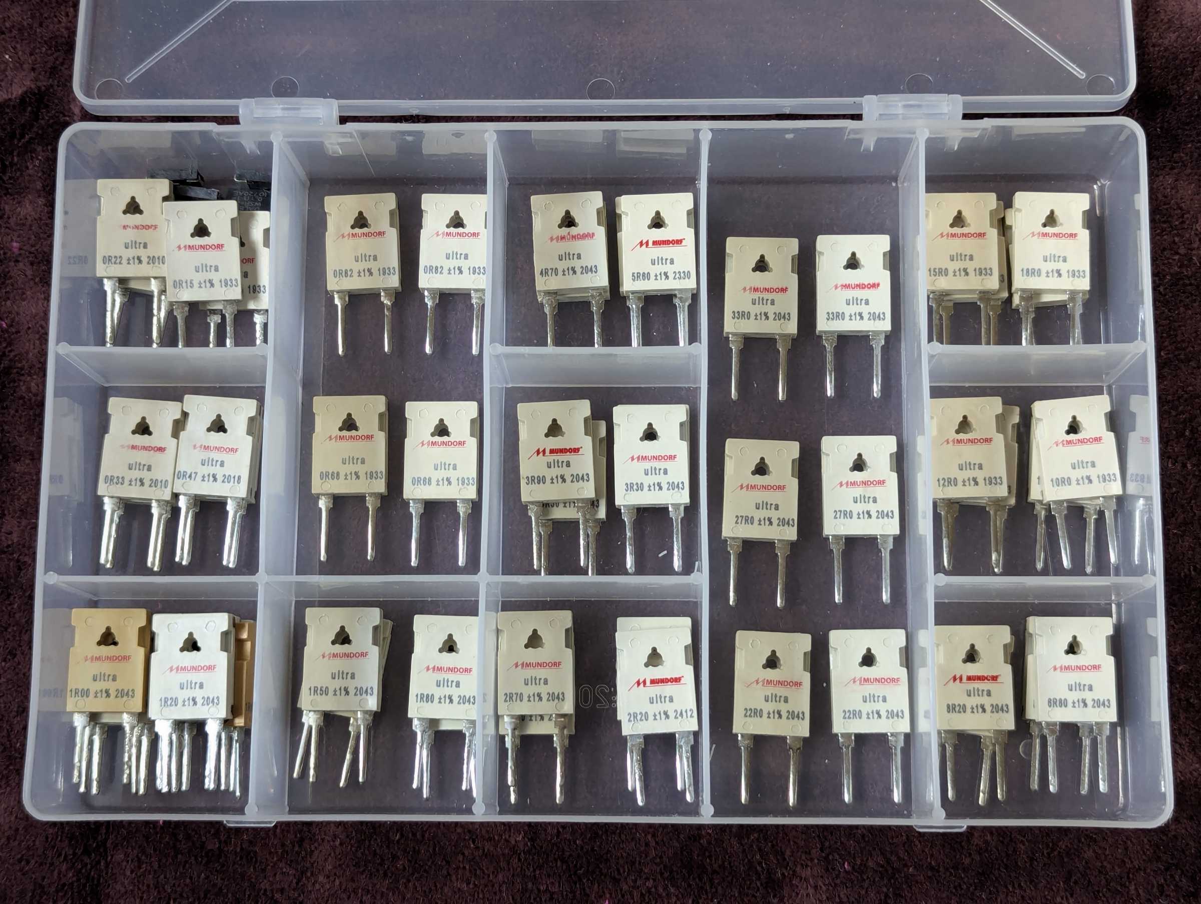
Despite its bulkiness, pretentiousness and high cost, MatriXover-III has fully met my expectations. Loudspeaker designing now takes much less time and effort, and has turned from a routine process into pure pleasure! Fewer mistakes, more iterations, and a better end result. Gone are the days when square meters of floor space were strewn with parts connected by very often falling off alligator clips, bundles of wires, boxes of parts, etc. All I need now is a pair of MatriXover-III and a couple of boxes of high quality resistors.![]()
![]()
Yevgeniy Kozhushko 19.11.2024
CONTACTS
- Ukraine
- (+380) 95 904 7827
- hificompass@gmail.com
LAST NEWS
-
27 Mar 2025
-
04 Mar 2025
-
25 Feb 2025
-
10 Feb 2025

