HiFiCompass
Test of a couple of iron core inductors
The problem
The disputes about what kind of inductors, iron or air cored, is better to use in the LF section of a loudspeaker crossover time to time arise in the network. Undoubtedly, air core coils have much better electrical specifications except the omic resistance (DCR) and at the same time have just shocking weight, size and cost parameters. Of course, it is always possible to decrease the DCR using a higher gauge wire or foil but after all we get a coil of gigantic size and price which is moreover a good low frequency magnetic field radiating antenna and not always can be placed inside a loudspeaker enclosure.
Generally speaking, if a woofer has low Qts, something less than 0.3, then an additional DCR of a LF coil in the crossover never make things worse and it is hardily possible to use an air coil with moderate wire gauge and overall size. We get uncompromising option here, all that we need to do is to take in account an effect of the additional DCR on Qts, sensitivity and the final enclosure volume at the stage of designing of a loudspeaker. This way enables to get a bit lower F(-3dB) by the price of small concession in sensitivity and size of the loudspeaker.
But what we should do if the speaker Qts is already quite high and hardly in agreement with the internal volume of the enclosure that we already have? Just with such a case I had to deal with when designing the next loudspeaker. LF speaker Lambda Acoustics TD15X with "Apollo" option, which has a more linear motor, has Qts=0.73 in the 165 liter closed type enclosure. It is on the verge of permissible. The crossover design asks for two coils of 3.3 mH and 5.6 mH. Naturally, I want to use air coils so as not to introduce additional nonlinearity in the circuit and not to spoil the TD15X speaker designers efforts. The estimations give us the air coils will have the next parameters:
5.6 mH - DCR=0.43 Ohm, wire diameter is near of 2 mm, overall coil diameter is 130 mm, height is 30 mm and the weight is 2.32 kg.
3.3 mH - DCR=0.31 Ohm, wire diameter is near of 2 mm, overall coil diameter is 110 mm, height is 30 mm and the weight is 1.62 kg.
The total weight is 7.7 kg, is it a joke? How about the placing of them in the loudspeaker box?
The total DCR of two connected in-serial coils give us 0.74 Ohm, that leads to Qts=0.81 and the sensitivity loss about 0.91 dB.
There is an alternative option - to use iron core coils "Sledgehammer" Steel Laminate 3.3 mH 15 AWG (DCR=0.185 Ohm) and "Sledgehammer" Steel Laminate 5.0 mH 15 AWG (DCR=0.24 Ohm). The 5 mH coil can be wound up to 5.6 mH by the 2 mm wire and get the DCR of 0.25 Ohm. In the end we are getting the total DCR of two coils by the order of 0.435 Ohm and Qts=0.78 at the sensitivity loss about 0.5 dB. The close analog of that coils are MCoil FERON (Mundorf) BS140 series coils. The both coils cores are made of high quality high permeable steel in a form of stacked plates of 0.35 mm thickness.
From the point of view of a final Qts sensitivity loss, size, mass and price iron core coils have unquestionable advantages over air core coils. But how about a quality wise? Will cored coils be saturated at high currents? How much will the nonlinearity of iron core affect the overall linearity of the speaker + coil system?
Ufortunataly, none of the coils manufacturer doesn't give any useful data regarding high current behavior of their products. Every loudspeaker designer faces up with that question and is forced to take on trust the manufacturer claims like "High current design". Well, it remains to do a laboratory work and close this question for yourself forever.
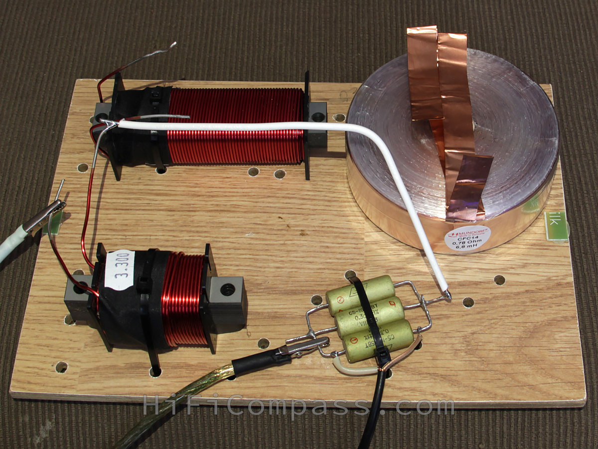
For this purpose a simple circuit for performing measurements had been made. The sinusoidal voltage was being applied from a power amplifier with a maximum output current, limited by internal protection to 8 A, to a series circuit of a test coil and an additional resistor of 0.1 Ohm in the form of three parallel-connected resistors of 0.3 Ohm with a power of 5 W. The signal from the additional resistor was being applied to a spectrum analyzer. The measurements were carried out at frequencies of 20, 50, 100, 200 and 500 Hz at currents from 1 to 8 A. As a reference the measurements of Mundorf CFC14 6.8 mH air foil coil was being used.
Below you can see the diagrams of the measurements. When analyzing the results take in account that the coil currents from 1 to 8 A through a load impedance (speaker) 4 Ohm (8 Ohm) correspond the next power levels:
1 A - 4 W (8 W for 8 Ohm)
2 A - 16 W (32 W for 8 Ohm)
3 A - 36 W (72 W for 8 Ohm)
4 A - 64 W (128 W for 8 Ohm)
5 A - 125 W (250 W for 8 Ohm)
6 A - 144 W (288 W for 8 Ohm)
7 A - 196 W (392 W for 8 Ohm)
8 A - 256 W (512 W for 8 Ohm)
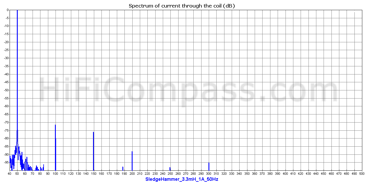
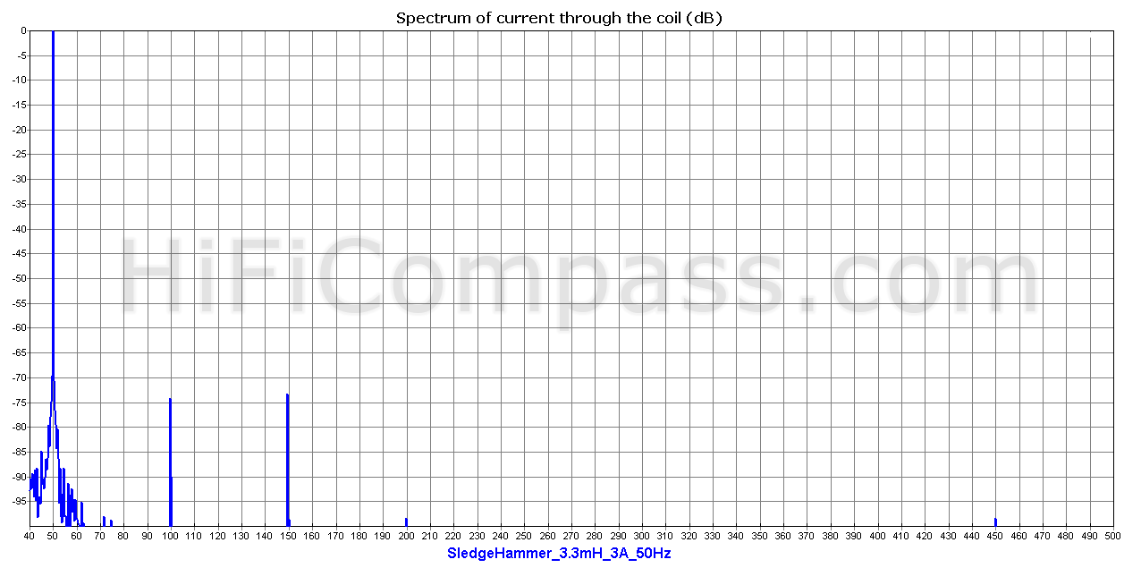
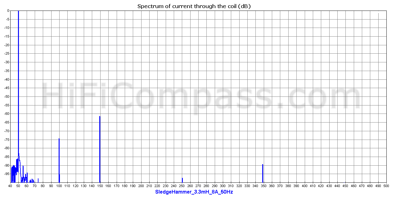
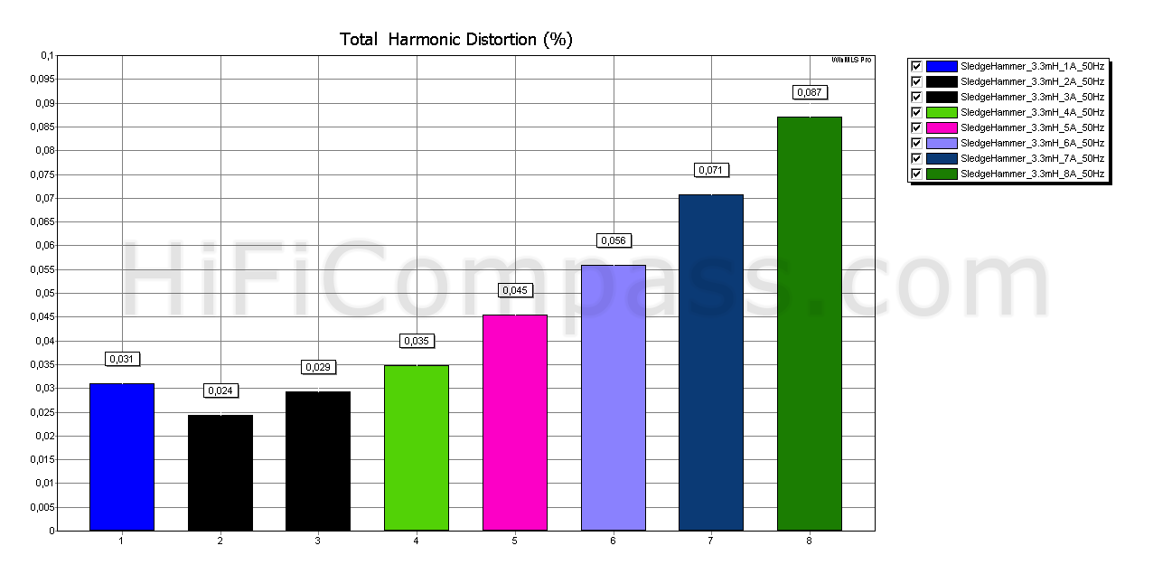
The measurements of Sledgehammer Steel Laminate 3.3 mH coil at 50 Hz
 |
 |
 |
The measurements of Sledgehammer Steel Laminate 3.3 mH coil at 100 Hz
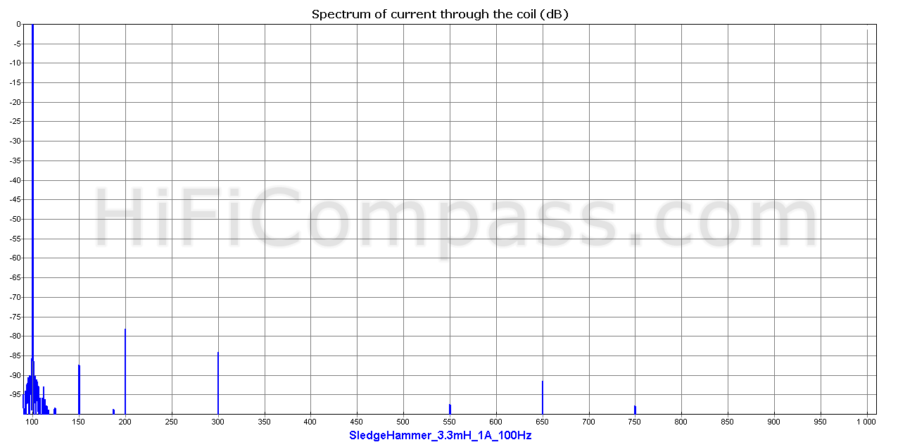 |
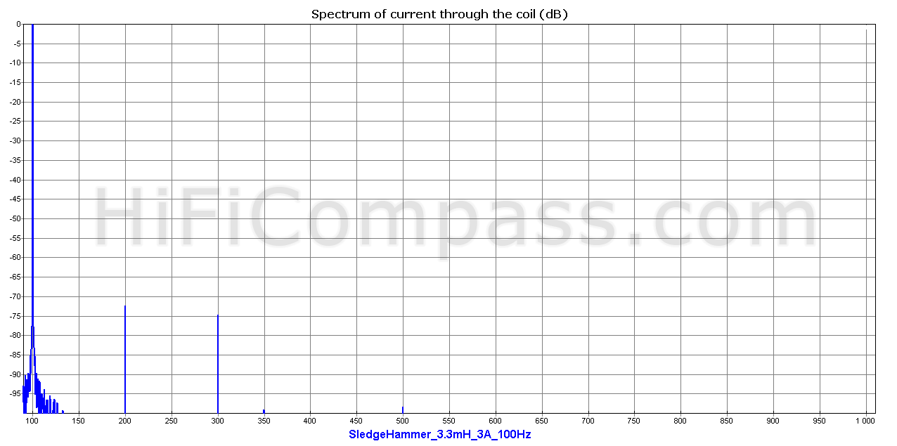 |
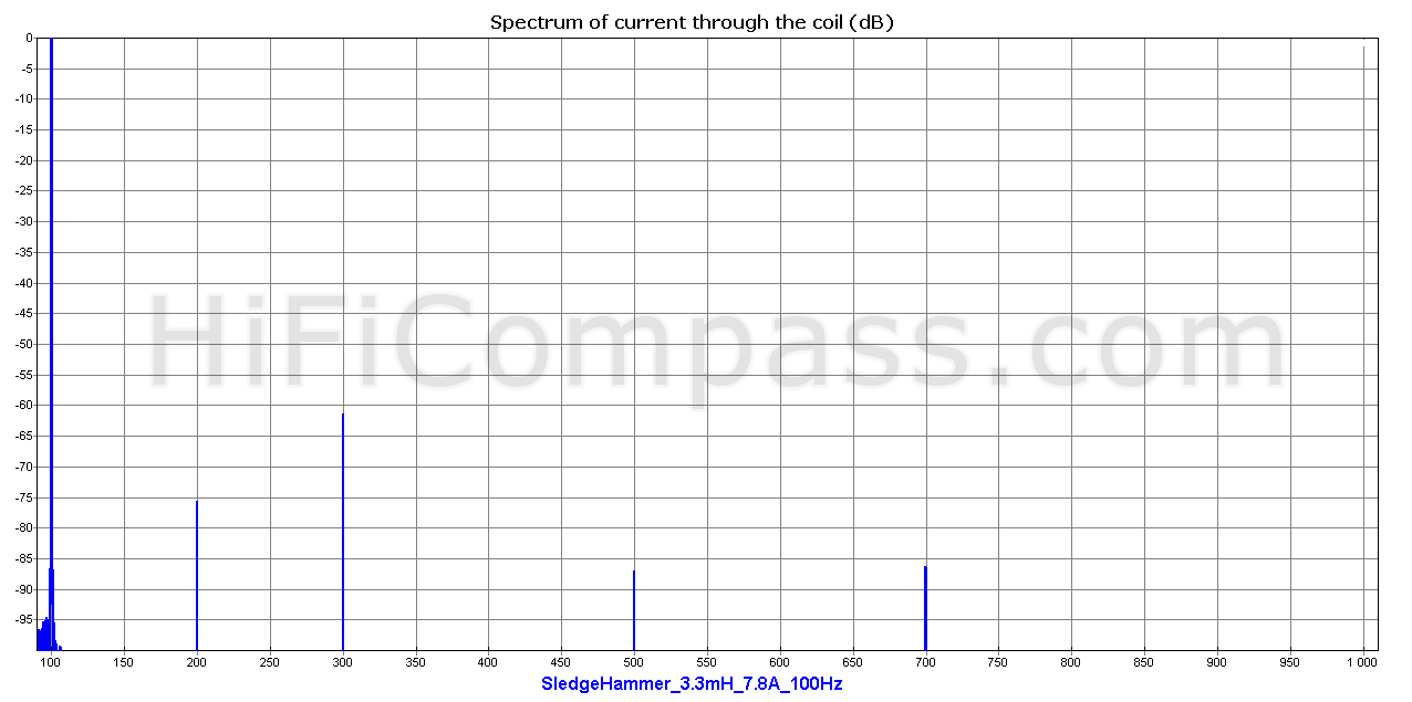 |
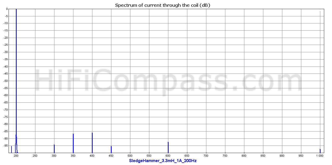
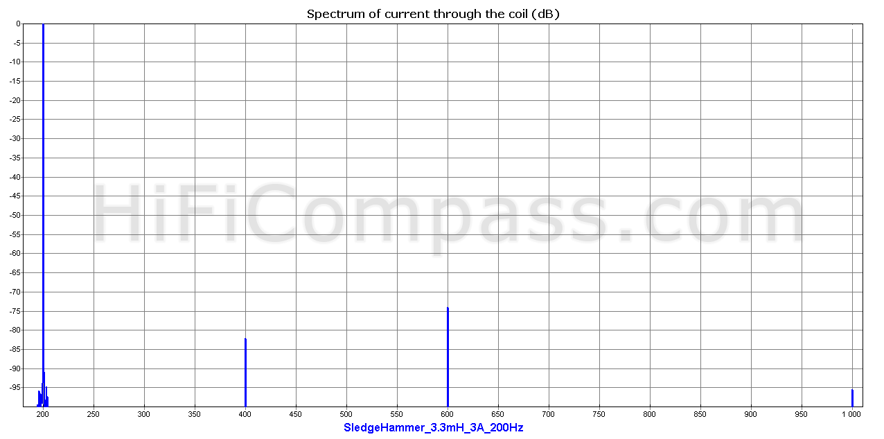
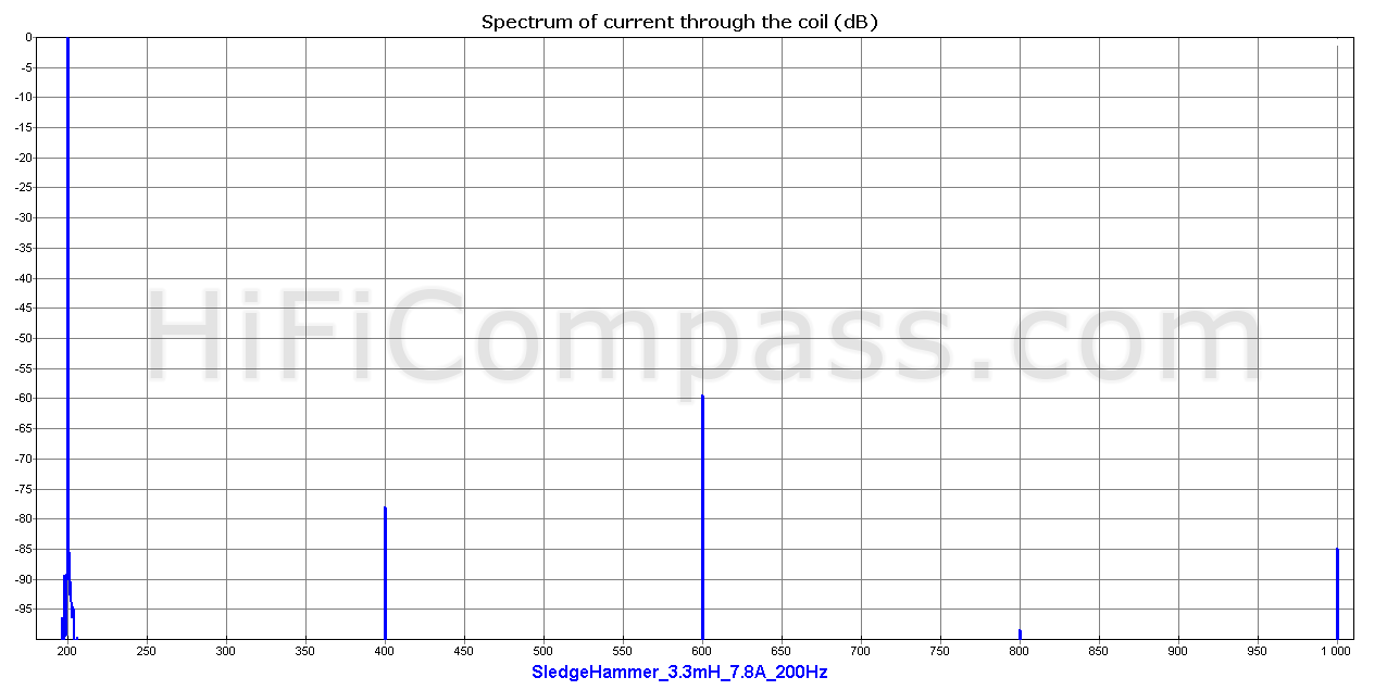
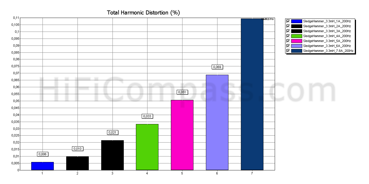
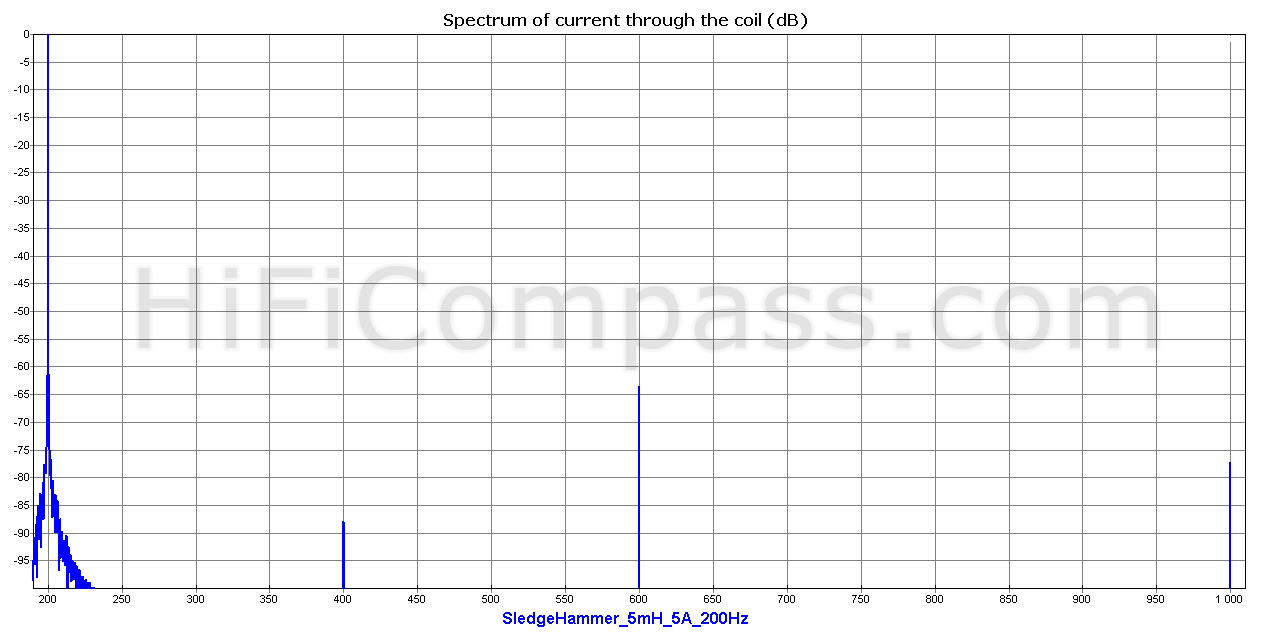
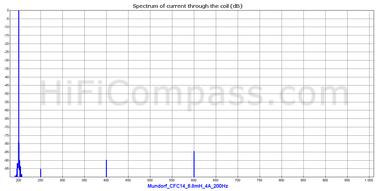
The measurements of Sledgehammer Steel Laminate 3.3 mH coil at 200 Hz
 |
 |
 |
The measurements of Sledgehammer Steel Laminate 3.3 mH coil at 500 Hz
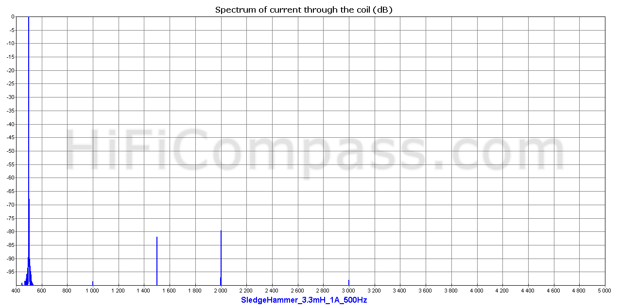 |
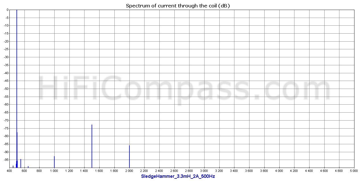 |
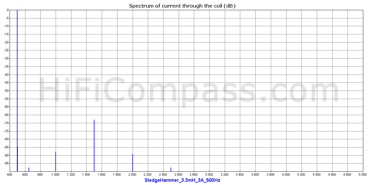 |
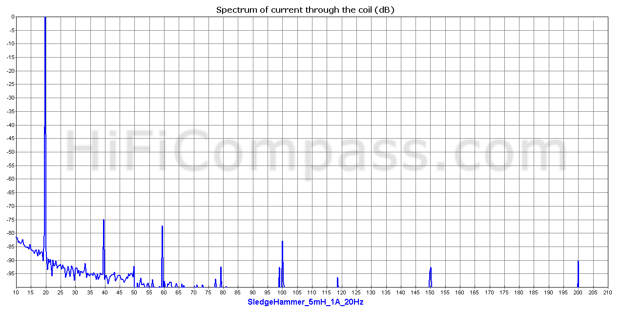
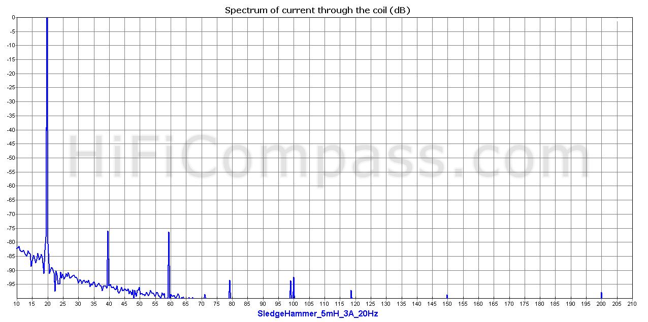
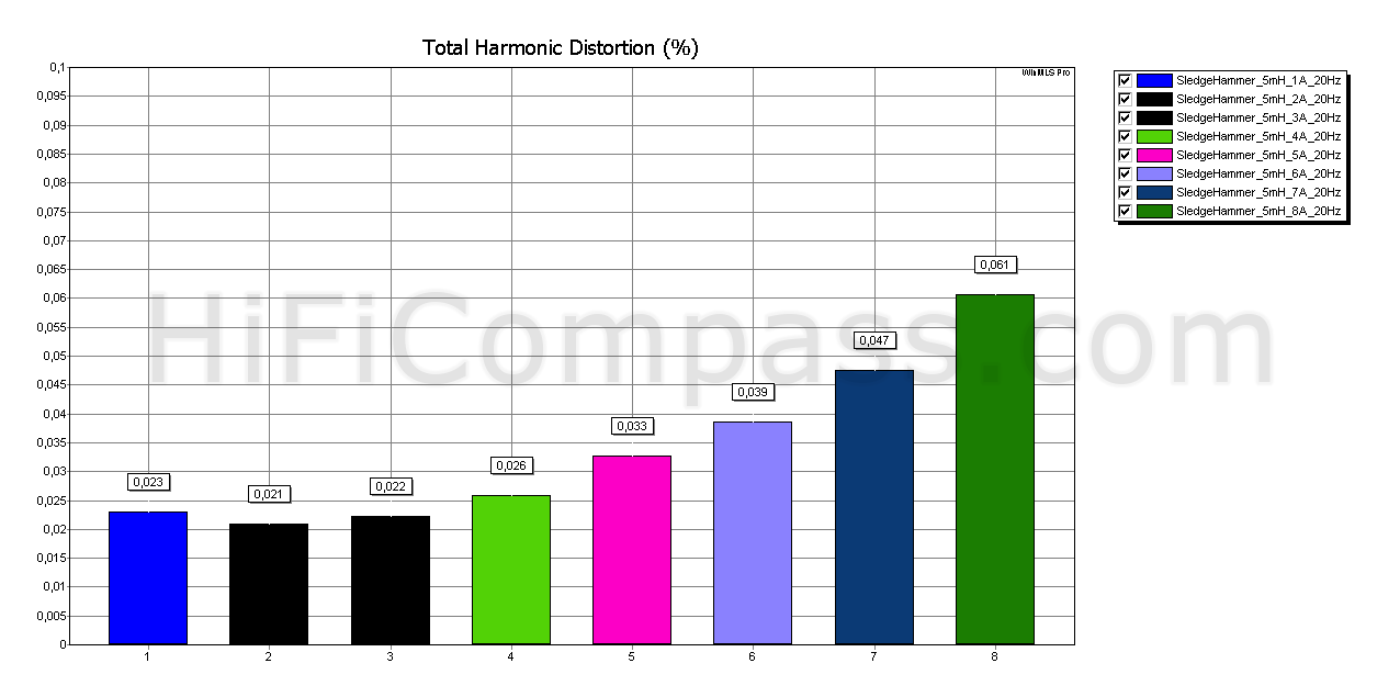
The measurements of Sledgehammer Steel Laminate 5 mH coil at 20 Hz
 |
 |
|
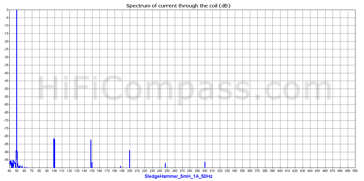
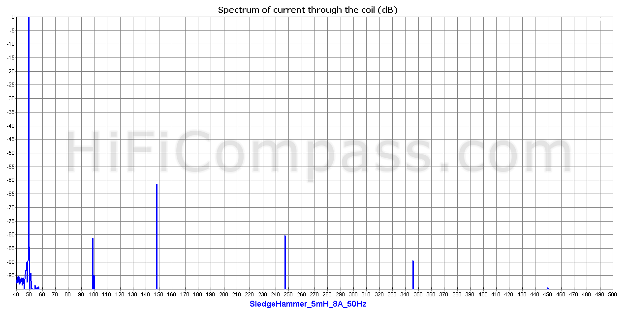
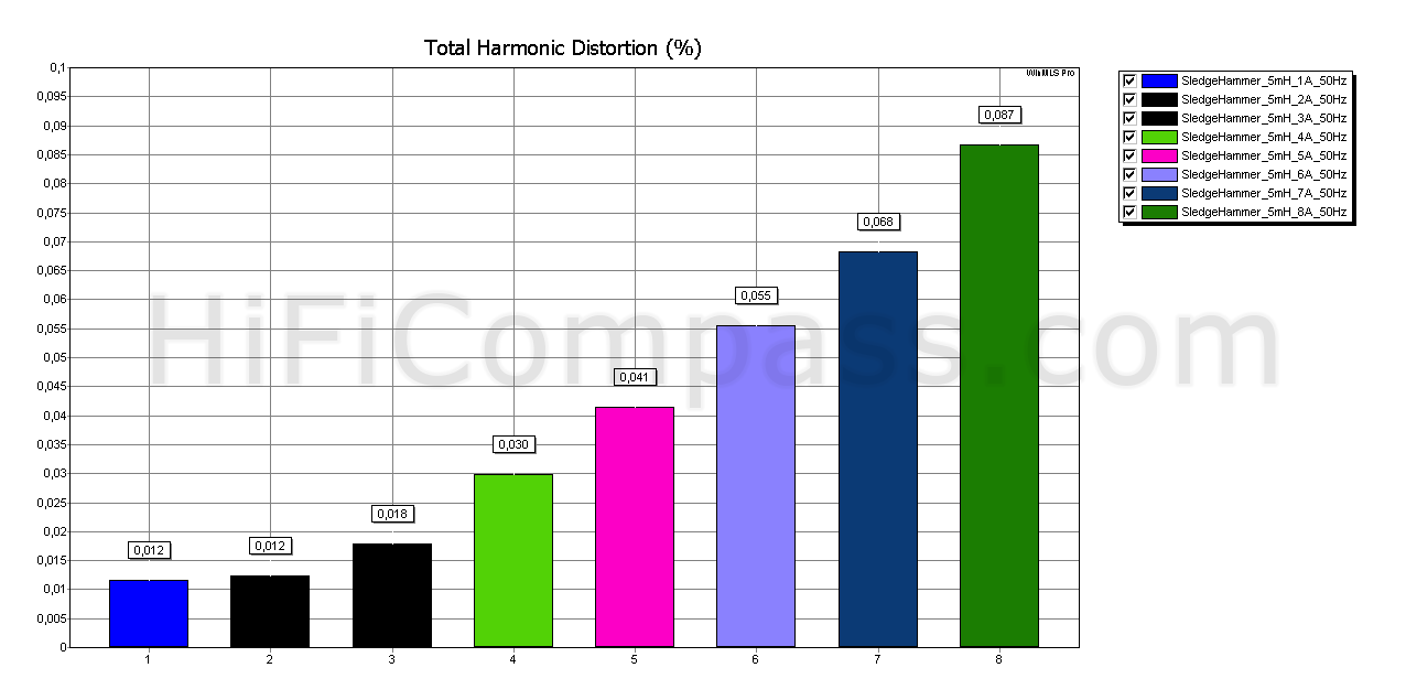
The measurements of Sledgehammer Steel Laminate 5 mH coil at 50 Hz
 |
|
 |
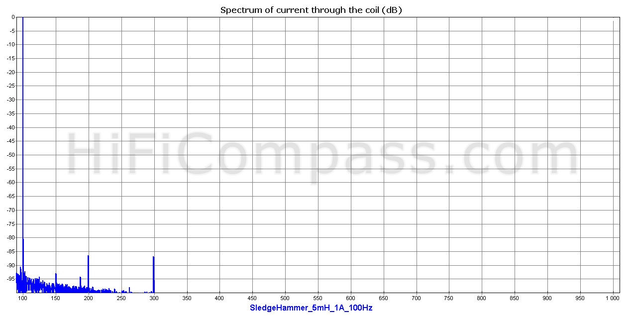
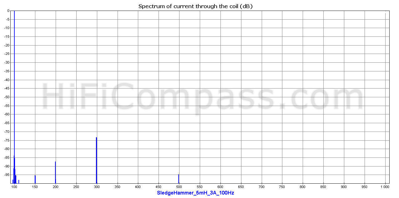
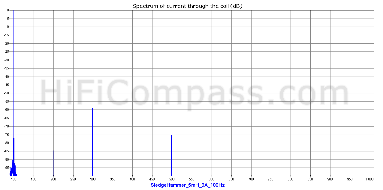
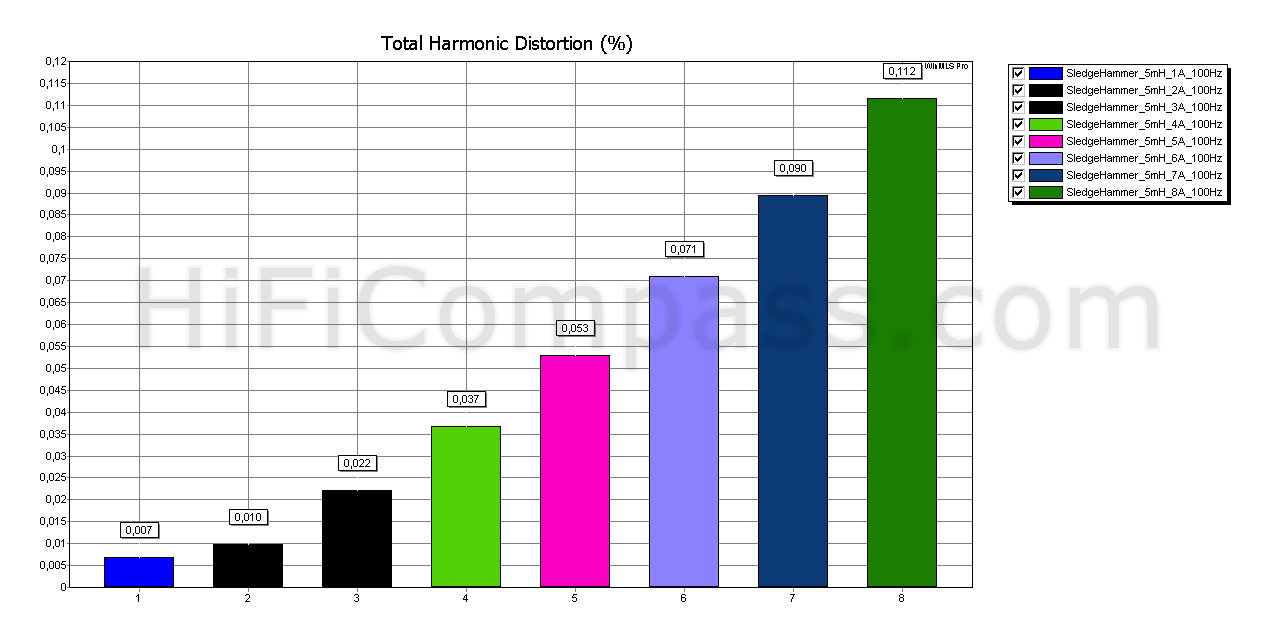
The measurements of Sledgehammer Steel Laminate 5 mH coil at 100 Hz
 |
 |
 |
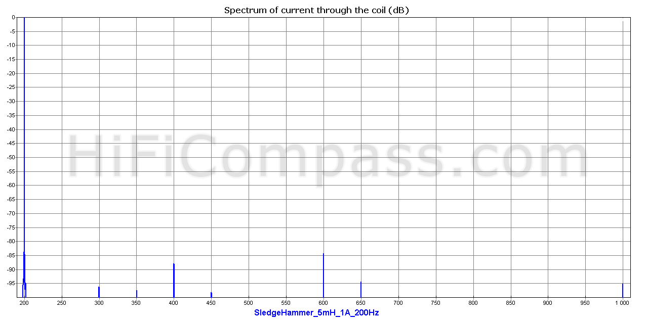
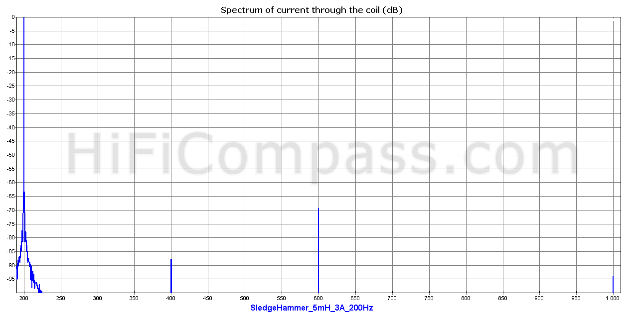
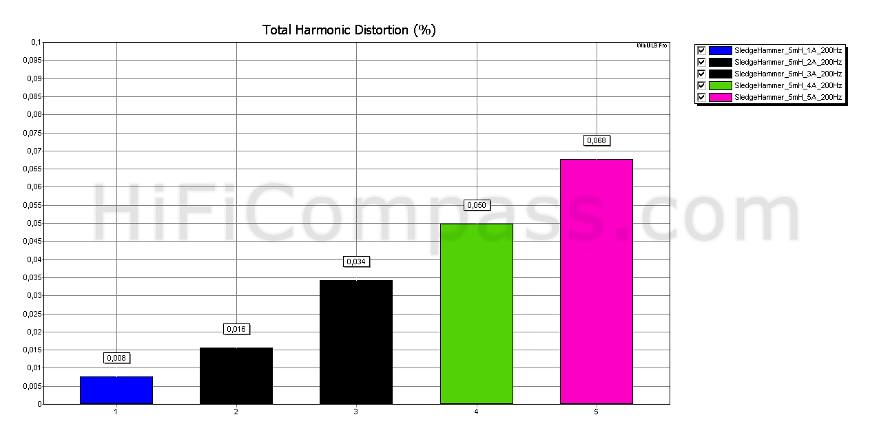
The measurements of Sledgehammer Steel Laminate 5 mH coil at 200 Hz
 |
 |
 |
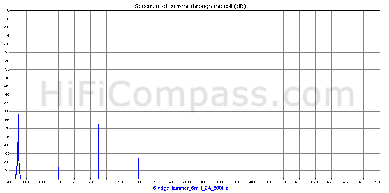
The measurements of Sledgehammer Steel Laminate 5 mH coil at 500 Hz
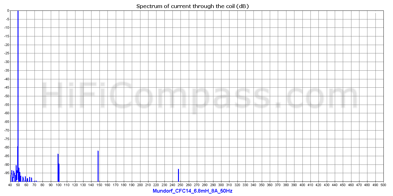
The measurements of Mundorf CFC14 6.8 mH air coil at 50 Hz/8 A and 200 Hz/4 A
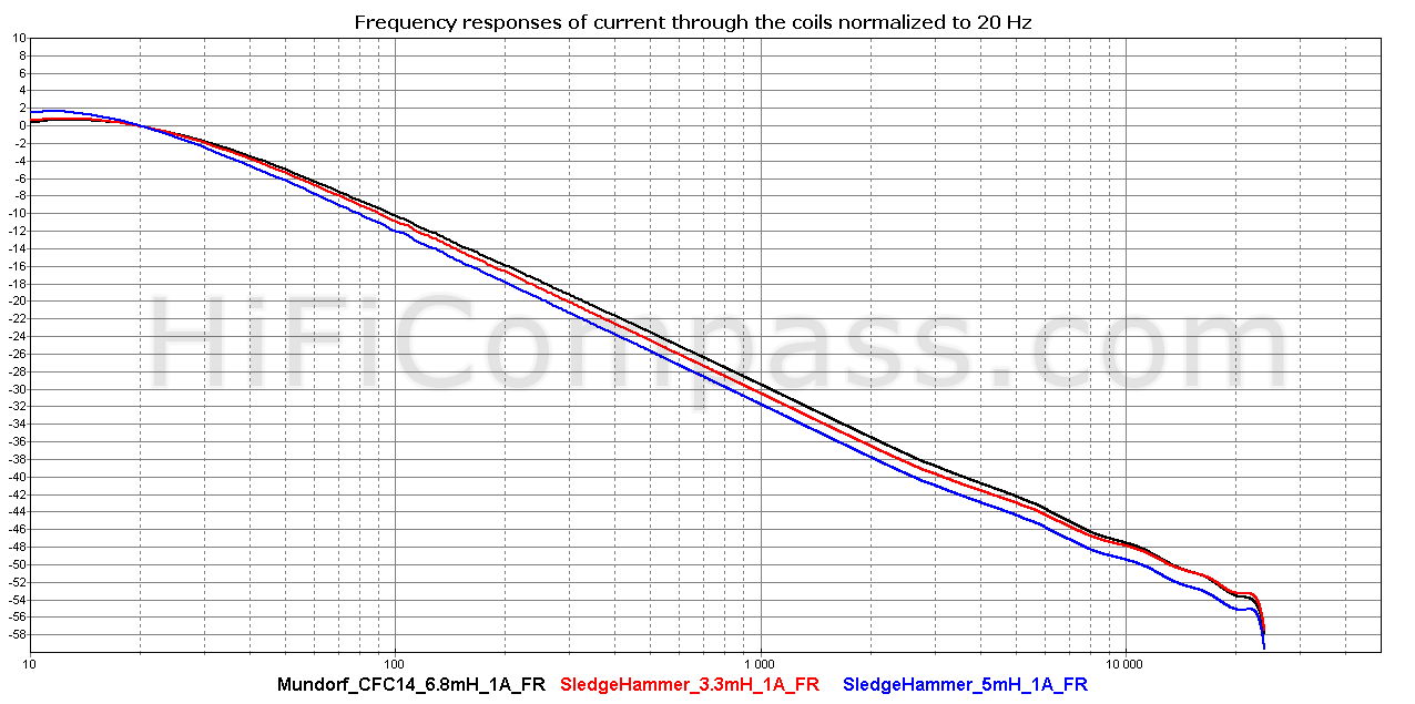
Frequency responses of circuits consisting Sledgehammer 3.3 mH, 5 mH and Mundorf CFC14 6.8 mH coils
Conclusions
So, what conclusions can be made from the analysis of that bulk of diagrams?
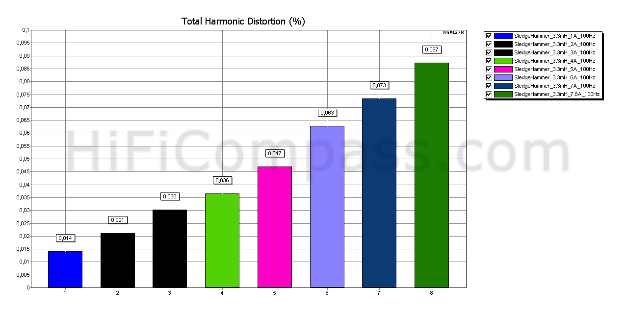
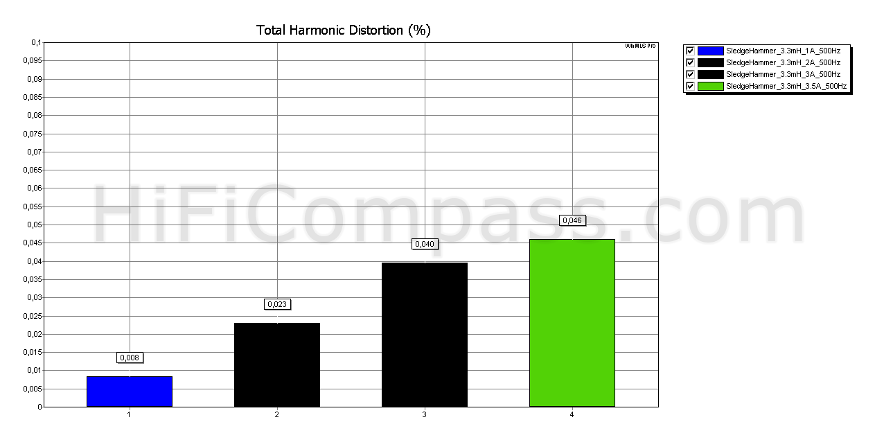
1. For the iron core coiles there is a tight correlation between a distortion level and current through the coil.
2. The distortion of air coils don't depend on the current.
3. Frequency responses of iron core coils and air coils in the frequency range up to 5 kHz almost do not differ from each other.
4. When frequency goes up from 20 Hz to 500 Hz the distortion of iron core coils slightly increase. For example, distortion of 5 mH cored coil increase in 2 times.
5. The minimum non-linear distortion level of one of the best in this regards speaker Lambda Acoustics TD15X at voltage level 11.2 Volt, which corresponds the current level about of 1.5 Ampere, is -50 ÷ -53 dB. At the same time the distortion level of 3.3 mH cored coil itself is -80 dB, and -76 dB for a 5 mH cored coil. Even at increasing current through the coil up to 8 A, which corresponds the power level in the load about 512 W, the cored coil distortion don't exceed -59 dB.
All this says about the iron cored coils like Sledgehammer Steel Laminate AWG15 and Mundorf MCoil FERON can certainly be used in LF circuits of high quality crossovers of loudspeakers, which incorporate the most linear LF speakers, without any risk to spoil the sound quality.


CONTACTS
- Ukraine
- (+380) 95 904 7827
- hificompass@gmail.com
LAST NEWS
-
04 Mar 2025
-
25 Feb 2025
-
10 Feb 2025
-
01 Feb 2025