HiFiCompass
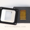
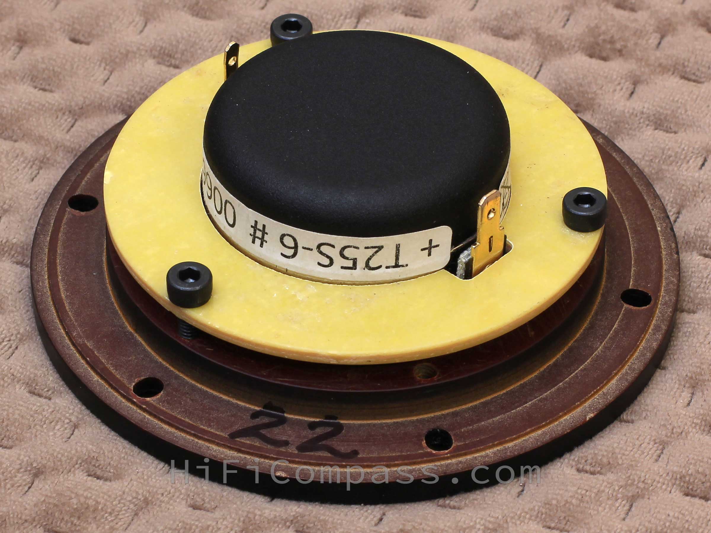
Waveguide WG104-XX/25 for the BlieSMa T25B-6, T25D-6, T25S-6 tweeters

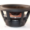
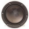
While working on the PuriBliss-BeWg project, a 150mm WG150-11 waveguide was developed for the BlieSMa T25B-6 tweeter. This is a relatively large waveguide and is designed to work with large (5"-6") midwoofers at low crossover frequencies. A waveguide of this size is not always necessary or even suitable for specific applications. There is often a need to match beryllium dome T25B-6 and silk dome T25S-6 tweeters with small midwoofers (3"-4"), and, in addition, there is a certain demand for tweeter upgrades in some commercial speakers, for which T25B-6 (T25S-6) are excellent candidates. In the latter case, a number of conditions must be met in order to match the directional patterns of neighboring drivers and the small flange of the new T25B-6 tweeter with the mounting hole of the loudspeaker's "old" tweeter.
Therefore, there was a need to design a new waveguide that should fulfill three main tasks:
1. Allow the modification of existing commercial speakers,
which use tweeters with a mounting flange diameter of 104 mm, one of the most popular mounting sizes among tweeters.
2. Reduce the imbalance in spatial sound dispersion between the 3-6 kHz and 10-20 kHz frequency ranges
This will measurably change the character of the sound field, increase the expressiveness of sound images and reduce the unpleasant emphasizing of sibilant sounds.
3. Correct the SPL frequency response of the T25S-6 silk tweeter in a natural acoustic way
This will avoid the use of a notch network in the crossover to suppress the hump in the top octave.
Increasing of sensitivity, reducing distortion in the lower treble range and decreasing of the time offset between a tweeter and cone midrange drivers by bringing their acoustic centers closer together in depth is not a priority for this design, but will be a pleasant bonus![]() .
.
The development of the WG104-XX/25 waveguide (the "25" at the end of the name means the relation to a 25 mm diameter diaphragm) was carried out using an iterative method, based on measurements of prototypes, analysis of their behavior and making adjustments to subsequent versions. The prototypes were made very precisely from laminated plastic (Phenolic Paper Laminate, SRBP – Synthetic Resin Bonded Paper) by CNC milling.
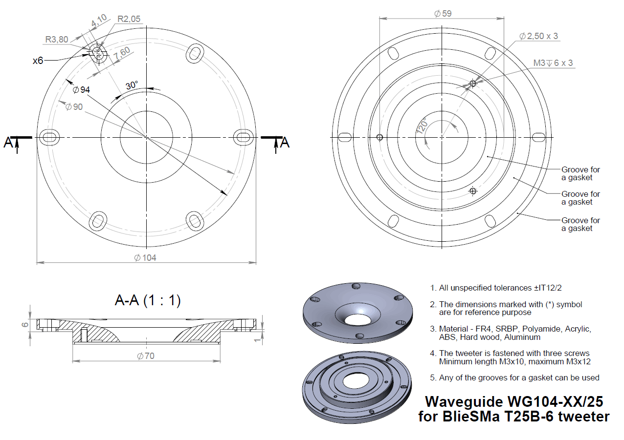
There is no single standard for tweeter mounting, so you can find tweeters with a flange diameter of 104 mm and mounting holes located on a circle of 90, 92 or 94 mm. The screw head pockets and mounting holes of the waveguide are elongated in order to accommodate these mounting patterns.
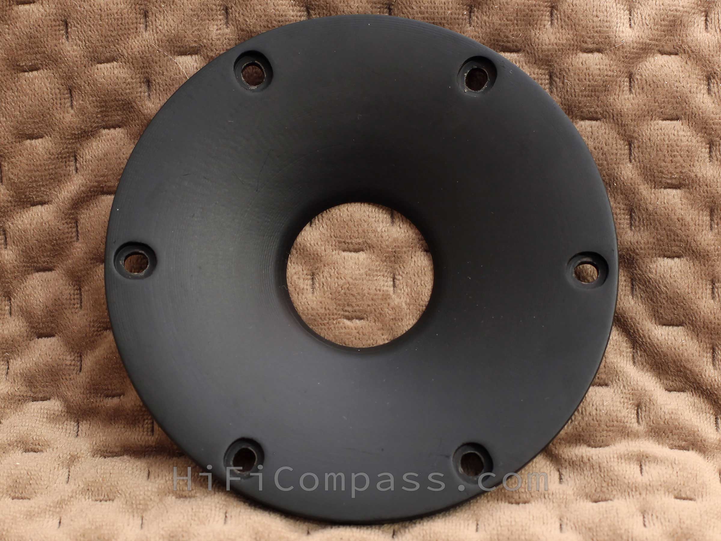
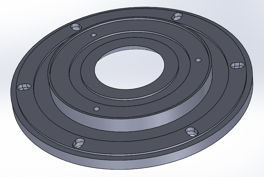
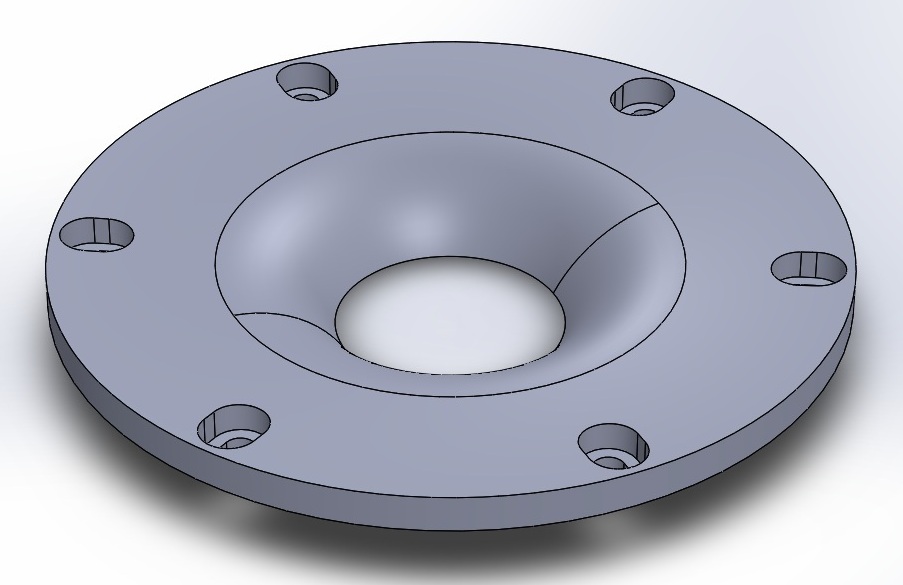
At the back of the waveguide flange, the outer edge of the waveguide has a narrow groove for a sealing gasket. The tweeter is mounted by clamping it with a rigid plate using three M4 screws. Some waveguide versions have more body thickness at the places where the original mounting holes of the T25B-6 tweeter are. This allowed it to avoid using an additional ring clamp and fasten the tweeter just with M3 screws through its mounting holes from the back side.
In practice, the waveguide can be made of any solid material (fiberglass, SRBP, acrylic, polyamide, hard wood, metal) by CNC milling or turning. 3D printing is also possible.
Measurements were made in a baffle of 1650x850 mm at a distance of 315 mm to a microphone. The measuring signal is a logarithmic sweep-tone with a voltage of 2.83 Volt. The measurement time window is 5 ms. Smoothing is 1/12 octave.
Below is an example of a version with the tweeter mounted with three M3 screws:

Below are diagrams of off-axis frequency responses - conventional and normalized, in which the axial response is taken as a reference, and the off-axis ones reflect only the difference with it:
.png)
.png)
The sensitivity over the entire range is in the range of 93-94 dB/2.83V*1m. The dispersion of sound energy is very wide up to 5 kHz, after which it starts to narrow smoothly until a bend at 10 kHz, after which the rate of directional pattern narrowing increases.
Waveguide for T25B-6 and T25D-6
Below are the off-axis frequency response diagrams for the three waveguide versions that are the final result of the development. Each version has its own characteristics that determine their behavior and application in loudspeakers. The waveguides are suitable for the beryllium T25B-6 and diamond T25D-6 tweeters due to the identical geometry of their diaphragms.
.png)
.png)
With the WG104-16/25 waveguide, the sensitivity varies from 98 dB at 4 kHz to 91 dB at 15 kHz. Despite the fact that the frequency response is humped, its behavior is very smooth and easy to correct even with a passive crossover. After linearizing of the frequency response, the average tweeter sensitivity will be around 91dB.
The point of dispersion narrowing has moved down from 5 to 2 kHz. The narrowing occurs uniformly and monotonically with frequency, which means that the DI directivity index increases uniformly with increasing frequency.
Comparing with the behavior of the tweeter's frequency response without the waveguide, it can be seen that the dispersion of sound decreased in the range up to 12 kHz and increased above 12 kHz, due to which there was some equalization of the balance of radiated sound energy between these ranges.
.png)
.png)
The waveguide effect is very close to WG104-16/25. The main difference is that WG104-17/25 provides slightly wider dispersion above 5 kHz.
.png)
.png)
The WG104-22/25 waveguide provides the widest sound dispersion among the three waveguide versions. In the 5 - 10 kHz range, a plateau on the off-axis frequency response is observed, indicating a constant DI directivity index here.
.png)
.png)
The tweeter's response is far from the easiest to work with, but it is operable. Sensitivity over the entire range varies between 92dB/2.5kHz - 90dB/7.5kHz - 94.5/13.5kHz. The dispersion of sound energy is very wide up to 7kHz, after which it begins to narrow sharply.
Below are the off-axis responses for the two final versions of the waveguide, each of which has a right to life. They differ from the beryllium tweeter versions due to the different diaphragm geometry:
.png)
.png)
Well, what can I say... The waveguide has done real magic![]() . The frequency response has acquired a characteristic shape with a clearly expressed maximum of 95.5 dB at 4 kHz. Starting from 8 kHz and up to 17 kHz, it reaches a shelf of 93 dB. Above 17 kHz, a decline begins at all angles - it's good that the ear already has poor hearing in this range, and all the high-frequency "goodies" are in the band up to 12-15 kHz.
. The frequency response has acquired a characteristic shape with a clearly expressed maximum of 95.5 dB at 4 kHz. Starting from 8 kHz and up to 17 kHz, it reaches a shelf of 93 dB. Above 17 kHz, a decline begins at all angles - it's good that the ear already has poor hearing in this range, and all the high-frequency "goodies" are in the band up to 12-15 kHz.
The dispersion narrowing point has shifted downwards from 7 to 2 kHz. The narrowing occurs stepwise with a plateau in the range of 6 - 10 kHz.
Comparing with the behavior of the frequency response of the tweeter without a waveguide, it can be seen that the sound dispersion has decreased in the range up to 10 kHz and has increased above 10 kHz, due to which there was some equalization of the balance of radiated sound energy between these ranges.
.png)
.png)
The WG104-18/25 waveguide, compared to the WG104-15/25, provides a slightly narrower sound dispersion and a more uniform and monotonic attenuation of the frequency response with angle and frequency, which is reflected in a smooth and monotonic increase in the DI directivity index.
.png)
.png)
.png)
.png)
.png)
.png)
.png)
.png)
.png)
.png)
.png)
.png)
.png)
.png)
.png)
.png)
.png)
.png)
.png)
.png)
.png)
.png)
.png)
.png)
.png)
.png)
.png)
.png)
.png)
.png)
.png)
.png)
.png)
.png)
What's on offer and what's the price
At the moment, a set of documentation required for self-manufacturing of the following versions of waveguides is offered:
- WG104-16/25 - for T25B-6
- WG104-17/25 - for T25B-6
- WG104-22/25 - for T25B-6
- WG104-15/25 - for T25S-6
- WG104-18/25 - for T25S-6
The documentation includes:
The cost of documentation for one version of the waveguide is 50 EURO. Payment is accepted only through the PayPal payment system. The documentation is sent to the buyer by e-mail within 24 hours of payment.
Send purchase requests to hificompass@gmail.com


CONTACTS
- Ukraine
- (+380) 95 904 7827
- hificompass@gmail.com
LAST NEWS
-
04 Mar 2025
-
25 Feb 2025
-
10 Feb 2025
-
01 Feb 2025