HiFiCompass
BlieSMa M142A-6 7" AlMg dome midrange

Today's long-awaited review was planned to be the first part of a three-part review of the new 7" dome midrange drivers from German company BlieSMa:
M142A-6 - with a aluminum diaphragm
M142P-6 - with a paper diaphragm
M142B-6 - with a beryllium diaphragm
However, due to the unexpected termination in the middle of 2023 of the production of a range of beryllium foil thicknesses by the US company Materion (practically the world monopolist in this industry), the production of the M142B-6 midrange driver was never launched, but was limited to a few pre-production samples presented by the company at the Munich HighEnd - 2023 exhibition. It's a pity, because the M142B-6 could have become a truly unique product...
Although this three-part review turns into a two-part review, it promises to be very interesting, as the M142A-6 and M142P-6 speakers are very interesting in their own right. Let's start with the aluminum M142A-6. I've held a lot of speakers in my hands, but I've never seen such a design before. It is a very large low-profile 7" midrange driver with an outward-turned, i.e. convex diaphragm of variable thickness made of aluminum-magnesium alloy, and a magnet system turned inward to the voice coil (so-called inverted magnet system). Agree, it is noticeably different from the usual ubiquitous classic designs - with a conventional basket, concave diaphragm and outer magnet. I'm sure that this is the first time you see such design too.
I am far from the idea that such a frankly unusual design was created with the sole purpose of simply surprising with its pretentiousness, it is too costly. Any new design always raises a question in my mind - what's the point of it and what is it for? Does anyone really lack the existing midranges on the market? The manufacturer himself helped us to answer this question by revealing the main ideas behind the M142A-6 midrange concept:
- Increasing the size of the diaphragm makes it possible to reduce the amplitude of its excursion at a constant sound pressure, which helps reduce the Doppler effect and all types of nonlinear distortions compared to smaller midrange drivers
-
A large diaphragm size always has the opposite effect of narrowing the radiation pattern and lowering the maximum upper operating frequency, so the convex dome diaphragm! Thanks to this, the directivity pattern is noticeably broadened and even outperforms "cone" competitors with smaller diaphragms
-
One more conceptual idea behind of BlieSMa M142A-6 midrange is working together BlieSMa T34A-4 and T34B-4 tweeters. The convex dome shape of the diaphragms of the midrange and tweeter contributes to a significant convergence of their acoustic centers in the direction of the main axis of radiation and approximation to a time-coherent loudspeaker
It seems to me that the above arguments are quite valid to "fiddle" with a non-traditional design.
I would like to express my great gratitude to Stanislav Malikov, the BlieSMa's designer and owner, for providing for testing the samples of M142A-6 and M142P-6 midrange speakers.
Here you can get familiar with the BlieSMa history.
What did the manufacturer state?
Getting familiar with the technical data sheet:
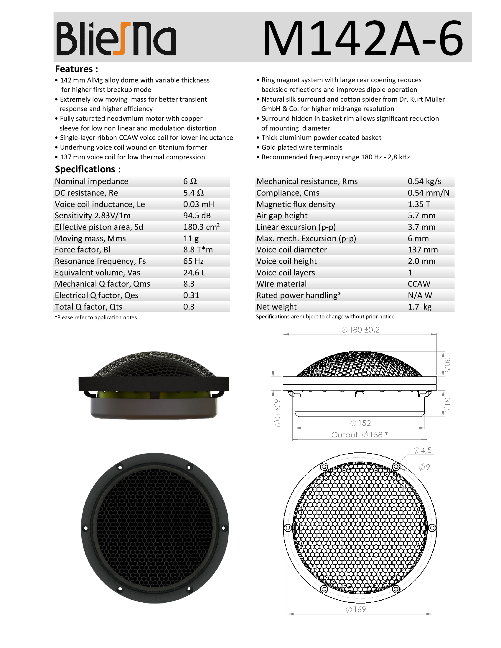
Of the numerical parameters it is worth to note the low mass of the moving system, only 11 grams at the radiating area of 180 cm2, very low inductance - 0.03 mH, high mechanical quality factor Qm=8.3 and huge diameter of the voice coil - 137 mm.
The sensitivity is quite high, 94.5 dB/2.83 volts. The linear excursion is small, only 1.85 mm per side, but this is compensated to some extent by the large diaphragm area and do not forget that this is a midrange, it does not need a large excursion as a bass driver.
Among the design features, I was pleased with a natural silk surround - for a true midrange speaker this is important, a huge single-layer voice coil with a ribbed wire, and an underhung-type motor with a copper sleeve.
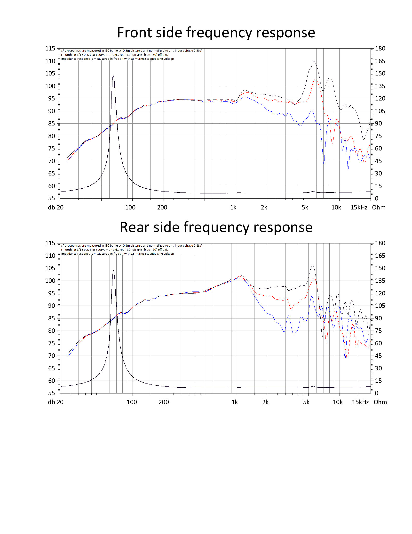
This is the first time I have ever seen a manufacturer provide additional frequency response graphs for rear radiation. They can be really useful for those who are considering using the speaker in an open design. As we can see, the "rear" characteristics repeat the "front" ones quite well, the difference is only in the range of 800 Hz - 2 kHz, but not more than 5 dB.
 |
 |
 |


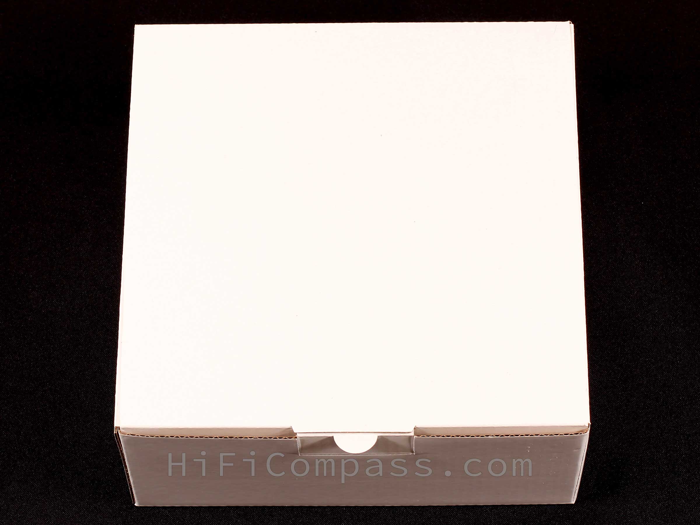
The ordinary but quite reliable package made of sturdy glossy corrugated cardboard. Inside, the speaker is fixed with cardboard inserts with shaped cutouts.
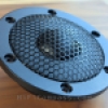
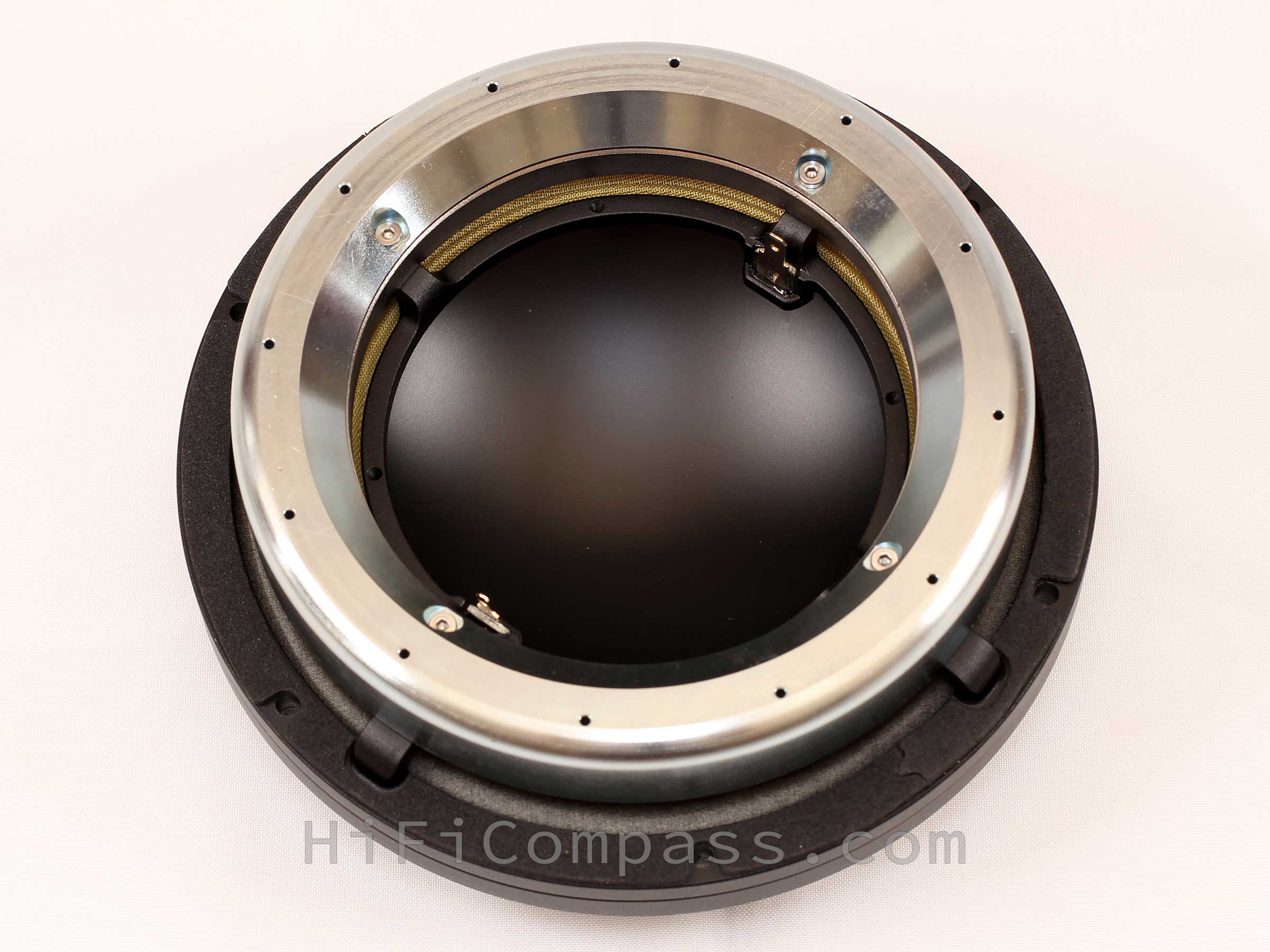
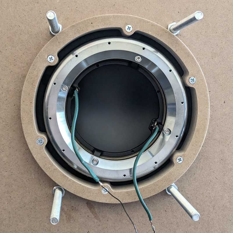
But the speaker itself is very far from an ordinary one. For the first time I took it in my hands and examined it from all sides, from different angles and even armed with a magnifying glass. What kind of a beast is this? A huge dome diaphragm behind a grille at the front, and a massive metal ring and a huge donut hole at the back - that's the whole speaker! I think the above pictures will make your brain work a little harder too.
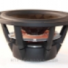
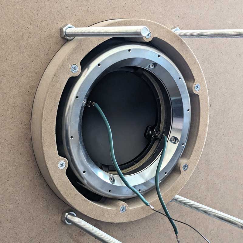
After 10-15 minutes of close examination, the puzzles of this design gradually begin to form in my head. The familiar basket has not quite the usual look - it is a 180-millimeter aluminum ring with a height of 7 mm with four thick, but very short legs, on which the underhung magnetic system is held. On the back side, the basket has a foam rubber gasket around the entire perimeter.
The magnetic system is a massive circular steel magnet core, encompassing a huge circular neodymium magnet on the outside, of which only the inner side surface is visible. There are 12 small holes around the perimeter of the magnetic core to provide ventilation for the voice coil, which is completely hidden in the magnetic gap and completely inaccessible to the eye. However, the 137(!) mm diameter titanium voice coil former, which is densely perforated, is clearly visible through the gap between the basket and the magnetic core.
The four-wave spider is made of natural cotton by the German company Dr. Kurt Muller. Such spiders are characterized by low mechanical losses and are particularly good for use in midrange speakers.
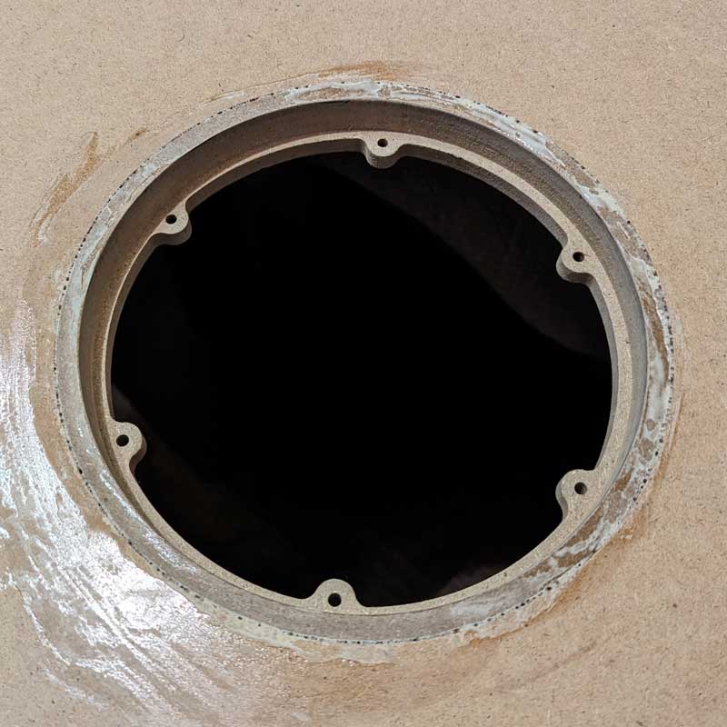
The half-roll inverted surround is made of natural silk, also by Dr. Kurt Muller. From the rear, it is very clearly visible in its entire size, but from the front it appears much narrower because it is partially covered by a thick, about 9 mm, aluminum ring to which the grille is attached. This ring has three main functions: decorative - it covers the joint between the surround and the basket, functional - it reduces the outward protrusion of the dome profile, and load-bearing - the grille is attached to it. It also has six holes with pockets for the heads of mounting screws.
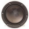
A black hole gapes through the huge opening in the magnet system - yes, yes, that's what the anodized aluminum-magnesium diaphragm looks like from behind, with a slight semi-matte silky sheen. From the front, it looks exactly the same. The convex profile of the diaphragm is quite high and protrudes about 25 mm from the basket.
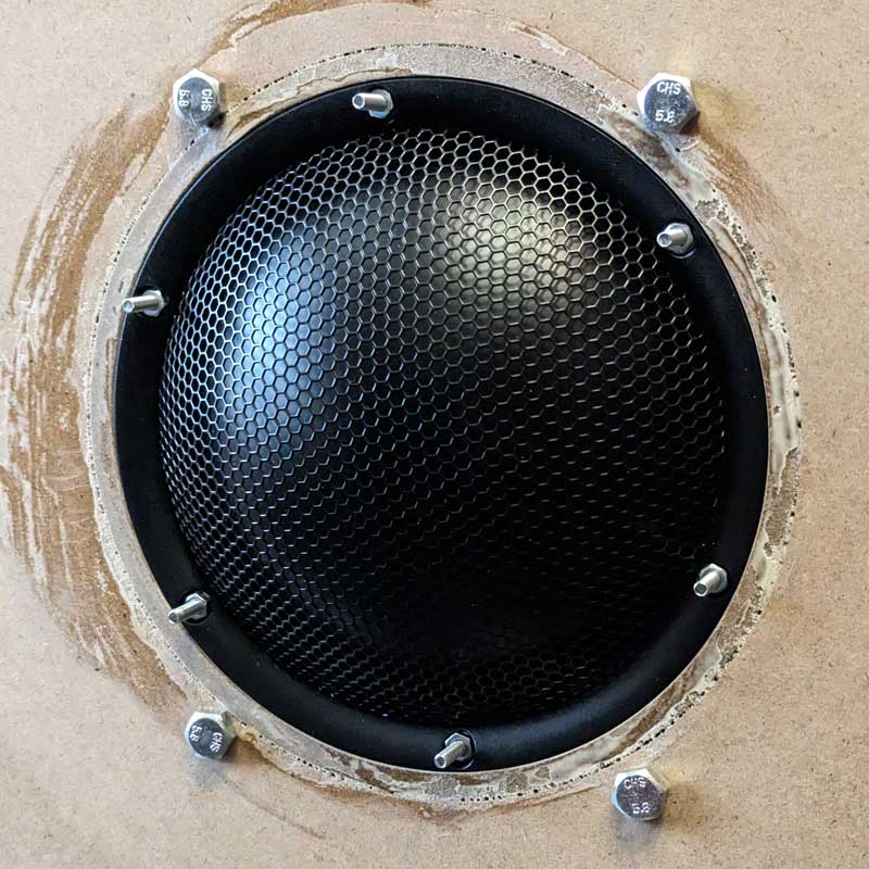
The diaphragm is protected by a metal grille with a high degree of transparency, at least 70%. The grille and all aluminum parts are protected by a durable semi-matte powder coating.
The workmanship is of the highest quality. No glue marks, scratches, dirt and dust, stains or dents on the diaphragm as well as no chips, gaps or dents on the diaphragm. Absolutely nothing to complain about.
In the hands, the M142A-6 gives the impression of a solid monolith. All components are absolutely inert when tapped, and there is not the slightest hint of any extraneous sound.
Overall, the speaker made a pleasant impression with its unconventional design and excellent workmanship.
The diagrams below show the frequency responses of the impedance at different scales:
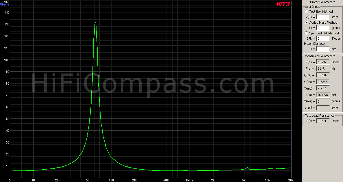
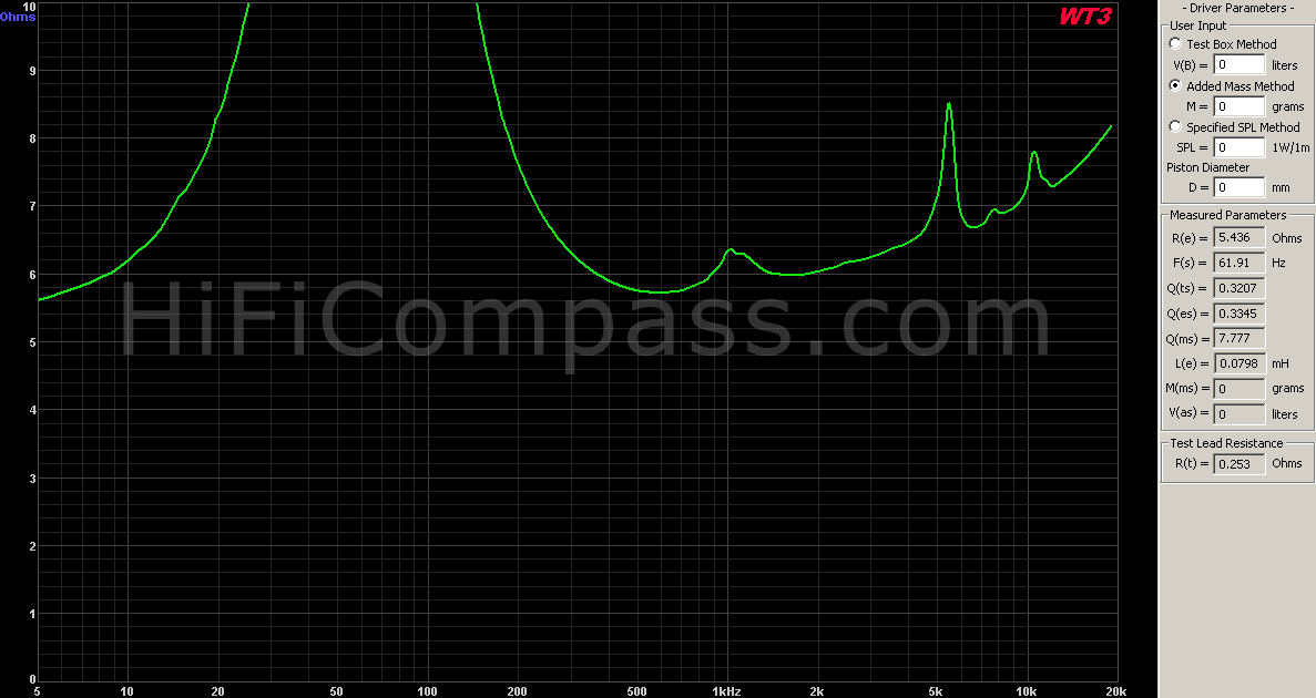
The measured values of the resonant frequency Fs=61.91 Hz and total quality factor Qts=0.32 are in good agreement with the datasheet, although these parameters are not particularly important for a midrange driver. Quite narrow impedance peak reaches 132 Ohm at the resonant frequency, which at low mass of the moving system indicates very low mechanical losses. And so it is - the measured mechanical quality factor Qms was as low as 7.77, just below the declared value of 8.3.
The impedance curve above 200 Hz is virtually flat, with a rise to 20 kHz relative to 500 Hz of less than 45%, reflecting the extremely low inductance of the voice coil. This low inductance (0.03 mH) is due to the short (2 mm) single-layer voice coil and the massive copper sleeve in the magnetic gap.
A series of bursts above 4 kHz accompanies the aluminum diaphragm breakups - quite natural and inevitable phenomenon. But the hump at 1 kHz is quite unexpected. Usually in this range there is always an echo of the usual resonance of the surround and the edge of the soft cone diaphragm, but in the case of M142A-6 this effect should be absent at all, because the diaphragm is rigid, and the interface between the surround and diaphragm is supported by a rigid titanium voice coil former. In fact, it is caused by an acoustic effect due to a parasitic Helmholtz resonator formed by the elasticity of the air in the diaphragm subdome space and the mass of air in the short "tube" of the magnet system. This is a very unpleasant effect, but we will return to it a little later.
So, the impedance measurements told us about a moving system with very low mechanical losses, a very good motor that promises low nonlinear distortion, and the presence of parasitic resonance in the subdome space.
On-axis frequency response (at 315 mm)
Below is the axial smoothed (1/12 octave) frequency response magnitude of the M142A-6 measured in a test baffle at a distance of 315 mm to the microphone at 2.83 volts:
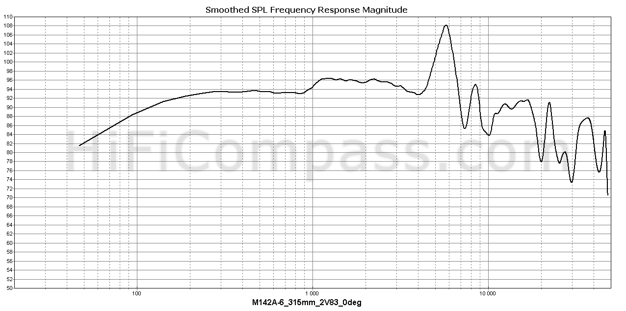
The frequency response is very close to the datasheet, but looks better in my opinion, because the step at 1 kHz has a more gentle character and lower height. In addition, the second resonance peak at 8.4 kHz is noticeably lower.
The measured sensitivity in the range from 200 Hz - 1 kHz averaged 93-93.5 dB, which is 1-1.5 dB below the claimed 94.5 dB.
Up to 4 kHz the frequency response is quite smooth, but it can't be called flat because of an unpleasant 3 dB step in the 1 kHz region. The first resonance of the diaphragm occurs at 5.5 kHz and is manifested by a spike of about 15 dB. Such a high frequency of 5.5 kHz of the first breakup for a lightweight aluminum diaphragm with an area of as much as 180 cm2 is an excellent indicator. Most likely, all factors - profile geometry, variable thickness and the mechanical excitation point of the diaphragm - played a role here at the same time. The first resonance is followed by a descending series of bursts and dips accompanying the breakup mode of diaphragm operation.
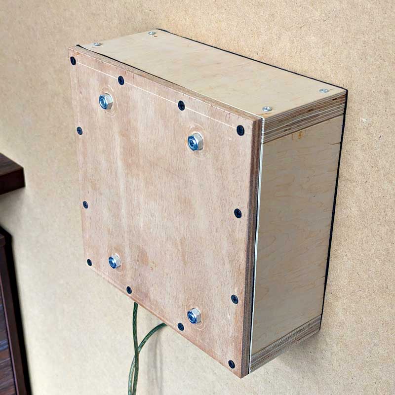
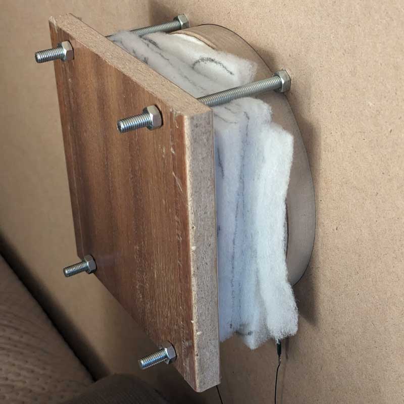
As you have already noticed, the M142A-6 midrange is not like any other. Its original design, while offering a number of advantages, faces problems that classic concave cone diaphragm designs never do. It is, of course, about the sub-dome resonance and its manifestation in the form of a step in the frequency response in the region of 1 kHz. This problem can be solved in the traditional way, indirectly, namely to fight the symptoms of the disease and elementary correct the step with the help of DSP in systems with active filtering, or do the same in a passive crossover, even if it is a little more complicated. Fortunately, the manufacturer does not leave us with the problem alone and for a non-standard speaker offers a non-standard approach, fundamentally eliminating the problem acoustically. The essence of the method, detailed in the document "M142 Series Application Note AN1", is to create a special acoustic load for the rear diaphragm radiation, neutralizing the parasitic sub-dome resonance.
As they say, trust but verify, so I decided to test the proposed method. The speaker was mounted in the test baffle, and a rear chamber was constructed from plywood and filled with sound-absorbing material in strict accordance with the apnote. In effect, the open-back speaker became a huge 7" dome midrange with a rear chamber:
 |
 |
 |
 |
 |
 |
Below are measurements of the speaker in the test baffle as is - the black curve, and with the rear chamber - the red curve:
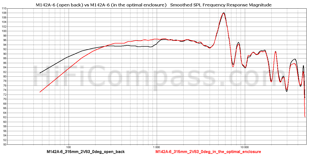
Wow, that's a completely different thing! The frequency response is magically transformed and became very smooth and even. The step disappeared completely, and the average sensitivity in the range 300 Hz - 3.3 kHz is already a very pleasant 95.5 - 96 dB. I can say that this uncomplicated method demonstrated an excellent result and allowed the speaker to reach its full potential!
Off-axis frequency responses (at 315 mm)
Below are graphs of off-axis frerquency responses - conventional and normalized, in which the axial response is taken as a reference, and the off-axis ones reflect only the difference with it:
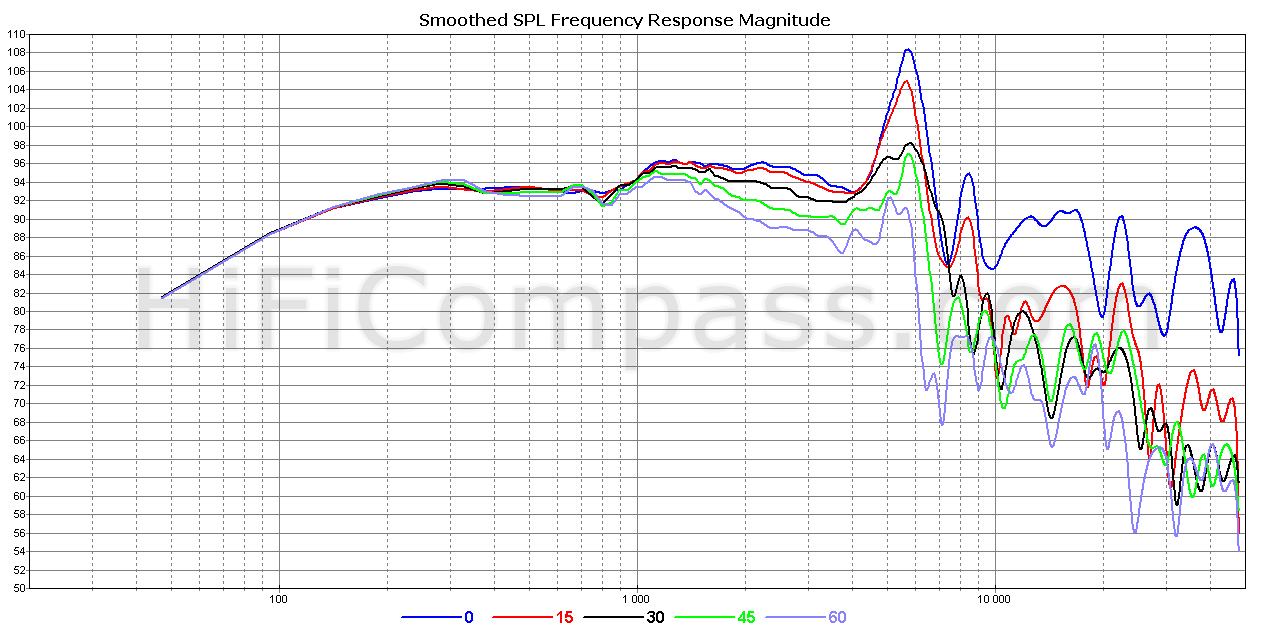

And here comes the main bonus of the large dome midrange - a very wide radiation pattern. Even at deflection angles of 60 degrees up to 4 kHz, the sound pressure does not drop below 6 dB in relation to the axial pressure. This is especially impressive when you consider that the diaphragm area is as much as 180 cm2.
From the normalized graph, it can be seen that starting at 1 kHz, the off-axis characteristics monotonically decline until about 2.2 kHz, after which the decline stops and they go on a shelf until 4 kHz.
Some cone speakers with a radiating area of even 119 cm2, especially above 2 kHz, cannot boast such a wide radiation pattern (for example, Satori MR16P-8, SB17NRX2C35-4, 16W/4531G06, C173-6-090).
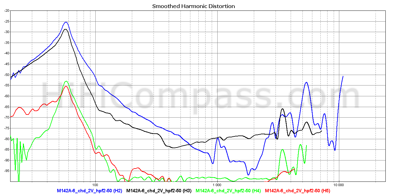
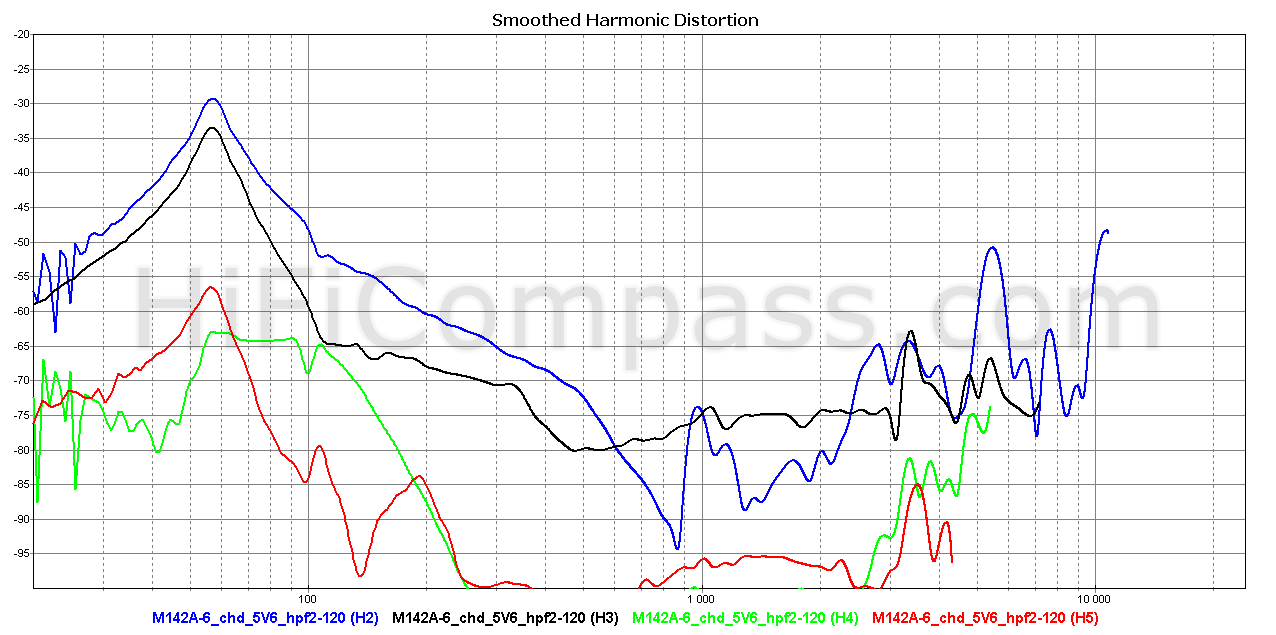
Harmonic distortion (at 315 mm)

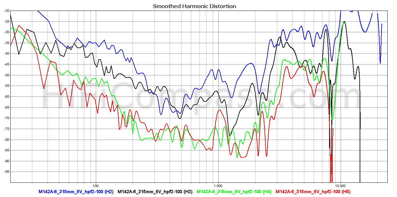
Above are the dependences of harmonic distortion at voltages of 2 and 8 volts, which corresponds to average sound pressure levels of 90.5 and 102.5 dB, respectively. The measurements were taken on axis at a distance of 315 mm to the microphone. To limit overloading of the speaker in terms of diaphragm displacement amplitude, a second-order digital high-pass filter with cutoff frequencies of 50 Hz at 2 Volts and 100 Hz at 8 Volts was used when measuring harmonic distortion. In these graphs, we analyze the frequency range only above 150 Hz.
At all sound pressure levels, an exceptionally sonorous second harmonic dominates the entire operating frequency range. The character of the harmonics is more or less even across the range, with no obvious bursts. The only exception is the 5th harmonic, which surges at 1 kHz. However, even at 104 dB of sound pressure, this bounce remains very narrow, and its level does not exceed minus 67 dB (0.05%).
Above 2.2 kHz, harmonics of all orders begin to rise sharply, so the frequency of 2.2-2.5 kHz can be considered the upper limit of the low pass filter cutoff frequency when using the speaker.
In general, I would characterize the level of harmonic distortion as very low in the 150 Hz - 2.2 kHz range.
Speakers with rigid diaphragms almost always have a strong spike in the frequency response corresponding to the first natural mechanical resonance of the diaphragm. With a mediocre motor, the voice coil current distortion harmonics from the frequencies that an integer number of times lower relative to the diaphragm's first resonance frequency receive additional amplification from the diaphragm resonance. For example, if the diaphragm resonance frequency is 5.5 kHz, then the 2nd, 3rd, 4th, and 5th current harmonics from the 2.75 kHz, 1.83 kHz, 1.375 kHz, and 1.1 kHz frequencies, respectively, receive amplification and will exhibit distortion value spikes at these frequencies. Good examples demonstrating this effect are measurements of Accuton C173-6-096, C173-4-091N, and C90-6-724 speakers. This phenomenon, its causes and methods of combating it are well described in the Low Distortion Filter for PTT6.5X04-NAA apnote by the Danish company Purifi.
In our case with the M142A-6 we have a rigid metal diaphragm and a resonance of 15 dB high at 5.5 kHz. However, most likely due to the very good motor and consequent low current distortion, there are no harmonic spikes at 1.375 kHz (for the 4th harmonic) and 2.75 kHz (for the 2nd harmonic). At 1 kHz there is a clear 5th harmonic spike and a 3rd harmonic spike can be seen around 1.83 kHz.
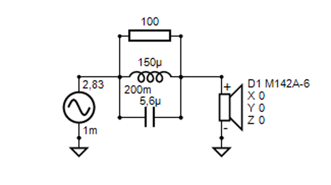
I decided to do a little experiment and check how the above-mentioned method of dealing with resonant amplification of voice coil current harmonics works in real life using the M142A-6 speaker as an example. In addition, I was interested to see the behavior of this effect when using a slightly different topology of a possible crossover. So, two circuits were assembled, one with only a 5.5 kHz parallel notch in series with the speaker, the other with one of the possible variants of a Linkwitz-Riley type 2nd order crossover with a cutoff frequency of about 1.4 kHz, but with a serial notch in parallel with the speaker and an inductance coil in front of the speaker:
 |
 |
 |
Below are frequency response measurements in the optimal enclosure (black curve), in the optimal enclosure + parallel notch (red curve) and in the optimal enclosure + crossover (blue curve):
_vs_Xover.png)
Let's look at the comparative behavior of the 2nd harmonic at 2.83 Volts:
-vs-M142A-6-(%2BXover)%2C-Optimal-enclosure---2nd-Harmonic-Distortion-compare.png)
As we can see, the second harmonic practically follows the frequency response and repeats its behavior.
-vs-M142A-6-(%2BXover)%2C-Optimal-enclosure---3rd-Harmonic-Distortion-compare.png)
But for the third harmonic, both circuits give full spike suppression at 1.85 kHz. Great!
Due to the lowering of the curves on the left and right, the peak at 3.3 kHz became very exposed and began to stick out.
-vs-M142A-6-(%2BXover)%2C-Optimal-enclosure---4th-Harmonic-Distortion-compare.png)
For the 4th harmonic, both circuits give good suppression at 5.5 kHz. The crossover gives lower 4th harmonic values over a wide frequency band due to the same reduction of signal amplitude in the stop band. The spike at 2.3 kHz is an artifact of the measurements and has nothing to do with the speaker, unfortunately it was detected late, already at the stage of measurement analysis.
-vs-M142A-6-(%2BXover)%2C-Optimal-enclosure---5th-Harmonic-Distortion-compare.png)
Unexpectedly, the 5th harmonic peak at 1 kHz was almost unaffected by any of the circuits. This means that the mechanism of its occurrence is not related to the resonant amplification of voice coil current harmonics, but has some other nature.
The rise of the 5th harmonic for a circuit with a crossover is illusory and is related to the form of data representation. The curve actually shows not the level of the harmonic itself, but its relation to the signal. Since the level of the harmonic itself is very low and drowns in the noise background of the measurement system, while the signal is heavily attenuated in the filter stop band, the harmonic/signal ratio shows a monotonic increase. Always keep this in mind when analyzing the values of relative level of harmonic distortion![]() .
.
So, to summarize. The M142A-6 driver exhibited resonance gain of only the third harmonic for a signal frequency of 1.83 kHz. Both circuitry methods for eliminating this phenomenon turned out to be equally effective. Measurements with the crossover clearly demonstrated how harmonic distortion in the stop band is reduced in real-world applications.
Voice coil current harmonic distortion
This type of measurement, although simple, is a good tool for evaluating the linearity of a speaker motor. The graphs above show the frequency dependencies of the 2nd, 3rd, 4th and 5th harmonics of the voice coil current at voltages of 2 and 5.6 volts (with the second-order high-pass filter on with cutoff frequencies of 50 and 120 Hz, respectively).
Voice coil current nonlinearity is the direct nonlinearity of the mechanical force driving the speaker cone, since this force is related to the current by a simple relationship F=B*L*I, where B is the magnetic field strength, L is the length of the voice coil wire inside the magnetic gap and I is the current. So, it is practically impossible to obtain sound pressure distortion lower than current distortion in the frequency range where the contribution of the motional nonlinearity becomes insignificant.
The overall level of current harmonics of all orders in the possible operating frequency range is very low. The second harmonic spikes around 1 kHz are a consequence of the acoustic subdome resonance. Above 2.2 kHz all harmonics show a very nervous and growing behavior, which is due to the diaphragm entering the breakup mode of operation.
The intermodulation distortion measurement is one of way of to analyze the device non-linearity. It is not an alternative, but an additional method and allows you to identify the spectral components of the inharmonious structure, which are much more harmful for high-quality sound reproduction and to which our hearing is more sensitive.
For testing I chose the frequencies with ratio (1:8.5). In this case the Doppler distortion is not yet dominant and the contribution of amplitude modulation can still be observed. The fractional coefficient eliminates the superposition of harmonic and intermodulation components on each other:
- 125 Hz and 1063 Hz
- 500 Hz and 4250 Hz
The graphs below show the intermodulation distortion spectra for voltages of 2 and 5.6 Volts.
However, in these plots products of the motor nonlinearity are mixed with products of inevitable frequency modulation due to the Doppler effect. How to determine who is who? We can analytically estimate the level of the first pair of the side Doppler components using the following formula [http://www.linkwitzlab.com/frontiers.htm#J]:
As(dB) = 20*log10(pi*A1*f2/c), where pi=3.14, A1- the modulating signal amplitude in meters, c=343 m/s, f2 - carrier frequency. In our case f2 =1063 Hz or 4250 Hz.
The amplitudes of the modulating frequencies (obtained by calculation) as well as the estimated maximum level of the second-order spectral components (IMA2Doppler) corresponding to Doppler distortions are:
- 125 Hz and 1063 Hz - these frequencies correspond to a quite real and most difficult mode of operation of the midrange speaker in terms of intermodulation distortion. 125 Hz signal stimulates maximum cone amplitude:
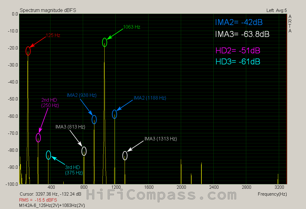

For voltages of 2 and 5.6 Volts, the measured IMA2 values were -42 dB and -32.9 dB, which is noticeably larger than the Doppler components of -50.7 dB and -41.7 dB, meaning that in the intermodulation distortion spectrum for the 125 and 1063 Hz frequency pair, amplitude modulation dominates over frequency modulation.
- 500 Гц и 4250 Гц

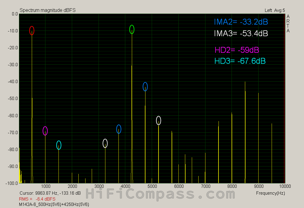
For voltages of 2 and 5.6 Volts, the measured IMA2 values were -40.6 dB and -33.2 dB, which are noticeably higher than the Doppler components of -59.1 dB and -50.1 dB, meaning that in the intermodulation distortion spectrum for the 500 and 4250 Hz frequency pair, amplitude modulation also dominates over frequency modulation.
Everything in this world is relative and in order to adequately assess the level of intermodulation distortion, it is necessary to have the correct reference point. The speakers of the Danish company Purifi are characterized by a very advanced design and, in my opinion, have the lowest nonlinear distortion to date. Therefore, as a reference I chose Purifi PTT6.5M08-NFA-01 6" midrange. The table shows comparative values of the second and third order intermodulation components IMA2 and IMA3 measured at the same sound pressure levels of the modulating signal:
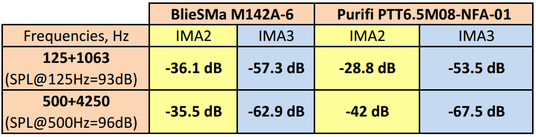
M142A-6 showed the best result for the frequency pair 125+1063 Hz, and PTT6.5M08-NFA-01 for the pair 500+4250 Hz. In a sense, it turned out to be parity.
So, in general, intermodulation distortion of M142A-6 can be characterized as "very low".

The step response rises up quickly and quickly returns to the rest state. It is quite spoiled by the oscillating process of the main diaphragm resonance of 5.5 kHz sitting on it. The picture is very far from nice looking, but after suppressing the resonance peak with the help of DSP with one biquad only, whose parameters are clear from the the graph, the situation improves and only ripples from smaller breakups remain:

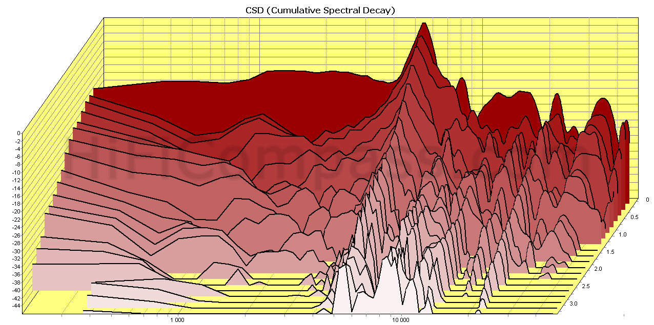
The waterfall shows the same effects as the step or freequency responses, in addition to exposing hidden resonances that are difficult to see on other types of measurements. In this case, you can clearly see the main diaphragm resonance at 5.5 kHz with a long tail and a series of subsequent small but also long breakups. The line between “good” and “evil” can be confidently drawn at approximately 3 kHz - below this frequency everything is absolutely clear, above iy there is an area of utter darkness, completely dotted with breakups:
And this is already a waterfall, but with the same notch filter, as in the case of measuring the step response. Everything is the same as before, but the first, most powerful crest is gone:
-waterfall.png)
After finishing all measurements, I took some time to listen to the M142A-6 mounted in the test baffle with the optimal enclosure according to the recommendations from the manufacturer's application note and the crossover connected. The crossover schematic and pictures of the setup are shown above in the review.
The overall timbre of the sound is very typical for speakers with aluminum diaphragms - not particularly colorful and rich in aftersounds, a bit dry. But the sound is very clean, detailed and transparent, dynamic and with perfectly conveyed energy. You can immediately feel the hardness of the diaphragm - the saxophone sounds very pushy and realistic. Yes, yes, it sounds really cool! It’s not even worth talking about percussion - this is the element of metal diaphragms. The piano is bright and a little synthetic, the bowed strings are bit simple, the vocals are good and neutral.
Parasitic manifestations of high-frequency diaphragm breakups were practically not noticeable, and if this range will be filled by a tweeter in a real loudspeaker, there is nothing to talk about. One can forget about any overloading of the speaker, even at very high volume level - everything is very clean.
The most intriguing question for me was whether the M142A-6 had some special character of sound due to its convex dome diaphragm shape and wide radiation pattern, because until then I had never heard such speakers.
Friends, I must say that it is there! It seemed to me that in comparison with speakers with usual cone diaphragms, the M142A-6 sounded more open, more relaxed, more spacious, less clamped in the upper midrange and less tied to the speaker itself.
With a very open and acoustically transparent magnet system at the rear, the driver has excellent prospects for open acoustic design applications.
So far, that's all I can say about my first subjective impressions after listening to the M142A-6 midrange.
Based on these measurements, I would recommend using the M142A-6 as the midrange of the highest quality loudspeakers in the 200Hz to 2kHz frequency range, preferably in the manufacturer's recommended design. In this application, the sensitivity of the driver is increased to 95 dB, the frequency response is equalized, and the low frequency roll-off is almost completely formed in a natural (acoustic) way, all that remains is to add the first electrical order to limit power and amplitude overload.
Since the M142A-6 has a convex dome diaphragm and was conceptually designed to be used in conjunction with BlieSMa T34A(B) tweeters, it is best used in conjunction with these tweeters, especially with passive filtering. In this case, it is much easier to ensure time matching of the drivers. With active filtering, with the possibility to adjust the delay time using DSP, your hands are completely free in terms of tweeter selection.
What is the price and where to purchase it?
The M142A-6 midrange is already on sale. The average retail price for the M142A-6 is €882/piece excluding VAT. You can purchase it in the following online stores:
- https://audio-hi.fi/en/bliesma_m142a-6-p-5375.html
- https://www.compacbel.be/boutique/#!/products/bliesma---m142a-6
- https://loudspeakershop.eu/glosnik-bliesma-m142a-6-almg-sredniotonowy-p-8331.html
- https://www.soundimports.eu/en/bliesma-m142a-6.html
- https://solen.ca/en/products/m142a-6
We got acquainted with a new, very interesting model of 7" dome midrange speaker by BlieSMa. The speaker is characterized by a very original design and a number of high technical characteristics. This is not my first review of BlieSMa products and I am once again convinced that each new product is a reflection of the company's firm philosophy in the matter of speaker design, namely minimizing the weight of the moving system, minimizing nonlinear distortion and maximizing the efficiency of the transducer. The M142A-6 midrange is another example of this.
So, what can be noted:
- dedicated midrange speaker
- high sensitivity - 93.5 dB/2.83 Volt*1 m (in the optimal enclosure up to 96 dB)
- titanium voice coil former
- huge 142mm AlMg convex dome diaphragm of variable thickness
- very wide radiation pattern
- very flat and smooth response in the optimum acoustic design
- very low harmonic distortion in the range 150 Hz - 2.2 kHz
- very low intermodulation distortion
- excellent workmanship
More detailed measurement results can be found here
Yevgeniy Kozhushko/20.04.2024


CONTACTS
- Ukraine
- (+380) 95 904 7827
- hificompass@gmail.com
LAST NEWS
-
27 Mar 2025
-
04 Mar 2025
-
25 Feb 2025
-
10 Feb 2025