HiFiCompass
Seas Excel 6" W18NX003 (E0096-08) midwoofer review
What is on the test bench?
Today our guest is again of the Scandinavian family - one of the oldest and legendary currently existing manufacturers of speaker drivers, the Norwegian company SEAS (abbreviation for Scandinavian Electro Acoustic Systems). The company's historical contribution to the development of the audio industry can hardly be overestimated. The range of speakers previously produced and being produced by it now is huge. The price range covers from the budget to the High-End segment. Here is a far from exhaustive list of more or less well-known brands that have used SEAS speakers in their loudspeakers:
Acoustic Energy, ACI, Amphion, Audes, Bamberg, Crystal Cable, Cary Audio, Chesky, Dynaco, Devore, Ex Machina, Ellis Audio, Gradient speakers, Grimm Audio, Hales, Harbeth, Jamo, Joseph Audio, Kudos Audio, Nomad Audio, MurphyBlaster Productions, MTZ Audio, North Creek Music, Nola, Opera, Penaudio, PMC, ProAc, Pass Labs, Ruark Audio, Siegfrid Linkwitz, Spendor, Sonus Faber, SONY, Salk Sound, Snell, Selah, Troels Gravesen, Totem Acoustics, Tyler Acoustics, Tidal, Usher, Vienna Acoustics, VAF, Verdant Audio, Von Schweikert, Wilson Audio, Zaph Audio, XTZ........
And this list continues to grow every year. By the way, about the years - in 2020 SEAS celebrated its 70th (!) Anniversary. It has come to this milestone fully armed, updating its Prestige and Excel speaker lines with new models with improved magnetic and moving systems. The issue of updating is long overdue. For example, the Excel line is the Everest of the company's products and used in the loudspeakers of highest level. The speakers of this line with unique magnesium membranes and an advanced magnetic systems at that time were released already in 1993. Twelve years after, the Excel line was extended with NEXTEL coated paper cone speakers based on the same motor as magnesium cone ones. By todays standards, when the development of highest quality speakers is unthinkable without the use of the latest electro-acoustic models and accurate software using FEM modeling, the time interval of 27 years is almost an eternity. During this time, many competitors entered the market with technically very advanced modern products (SB Acoustics, Satori, Scan-Speak, Purifi, BlieSMa).
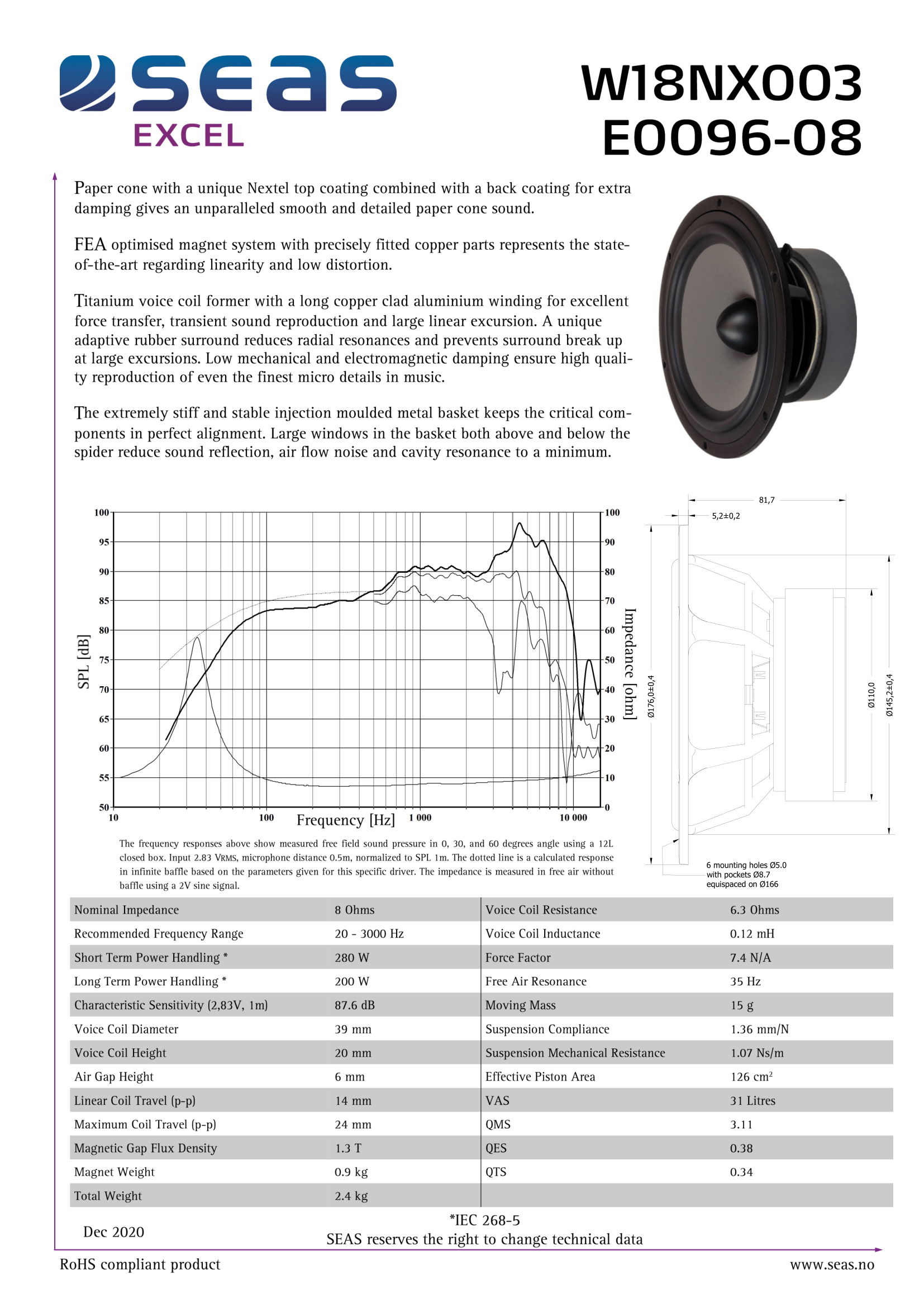
In today's review we take a close look at the newest model in the Excel line - the 6 "midwoofer W18NX003 (E0096-08) with paper cone and NEXTEL coating. It is the successor to the very popular W18NX001 (E0042-08S), which has been updated with the moving and magnet systems to match with a modern understanding of the technical excellence of the speakers. In December 2020 renowned Danish loudspeakers designer Troels Gravesen published the first short review of this model.
In the next review we will get acquainted with a smaller version of W18NX003 (E0096-08) - 4 "midwoofer W12CY006 (E0091-08).
You can read about the history of SEAS here.
Why do we test this?
SEAS has kindly provided a couple of its newest models for independent testing:
6" midwoofer W18NX003 (E0096-08)
4" midwoofer W12CY006 (E0091-08)
I would like to express my deep gratitude to SEAS company and personally to Claus Futtrup (Chief Techical Officer of the SEAS Sales & Marketing Department), as well as Andrey Romanov (Owner and CEO of FINSTOR Oy - www.audio-hi.fi) for their assistance in the implementation of this series of reviews.
What did the manufacturer state?
In general, the whole set of parameters is very balanced and very close to the previous model, which makes it easier to potentially upgrade existing loudspeakers based on the W18NX001 (E0042-08S).
Of all the parameters I would like to note a fairly decent linear stroke - 7 mm in one direction, and a very low inductance for an 8-ohm midwoofer - 0.12 mH, which is noticeably lower than that of its predecessor W18NX001 (E0042-08S) - 0.43 mH. The mechanical quality factor has increased from Qms = 2.08 to 3.11 in comparison with the same model, but is still not very high. The reason lies in the adaptive rubber suspension with increased mechanical losses (Rms=1.07 kg/s). The new version has been equipped with a stronger motor, the magnetic induction in the gap has increased by 30% (1.3 Tesla versus 1 Tesla).
The features and parameters given in the datasheet leave no doubt that we are dealing with a modern high-end midwoofer!
Visual inspection
 |
 |
 |
 |
 |
 |
 |
 |
 |
 |
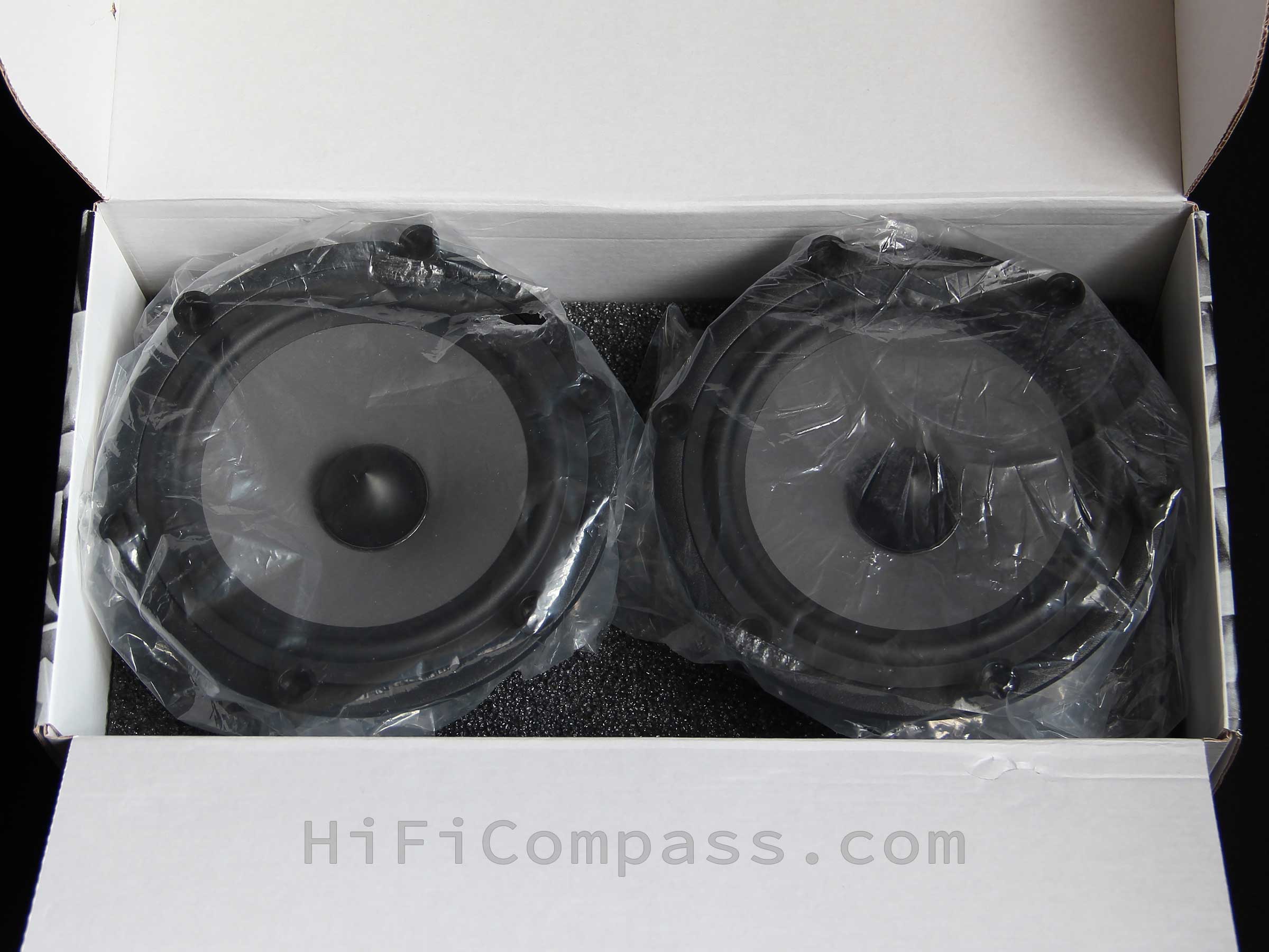
The midwoofers W18NX003 (E0096-08) are supplied in a matched pair in a reliable corrugated cardboard box with prints and logos of a corporate style. Inside the box the speakers sit firmly in the pockets of foam polyethylene. The plastic spacers in the basket mounting holes protect the speaker surrounds from unwanted contact with the package and squeezing.
-
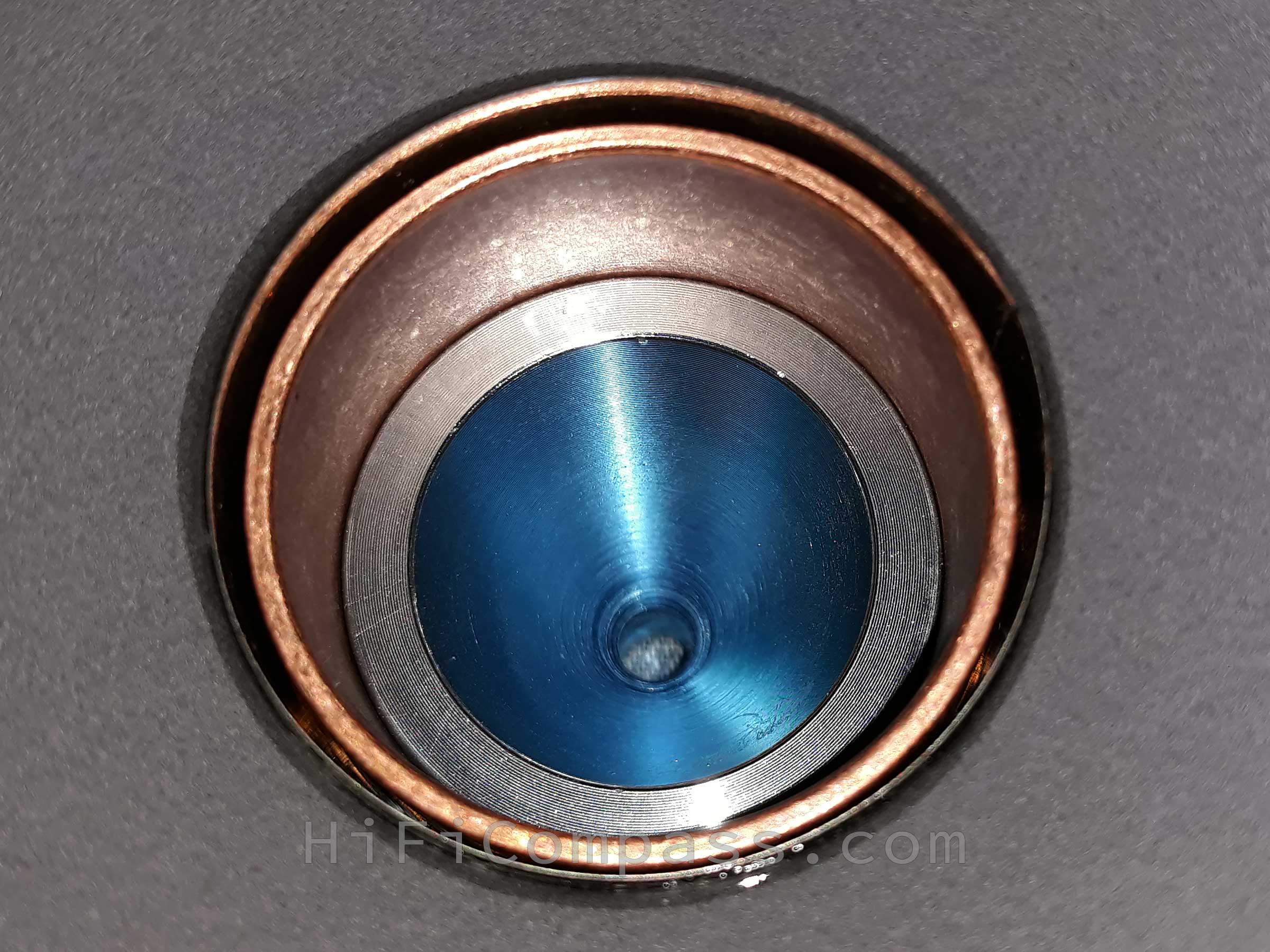
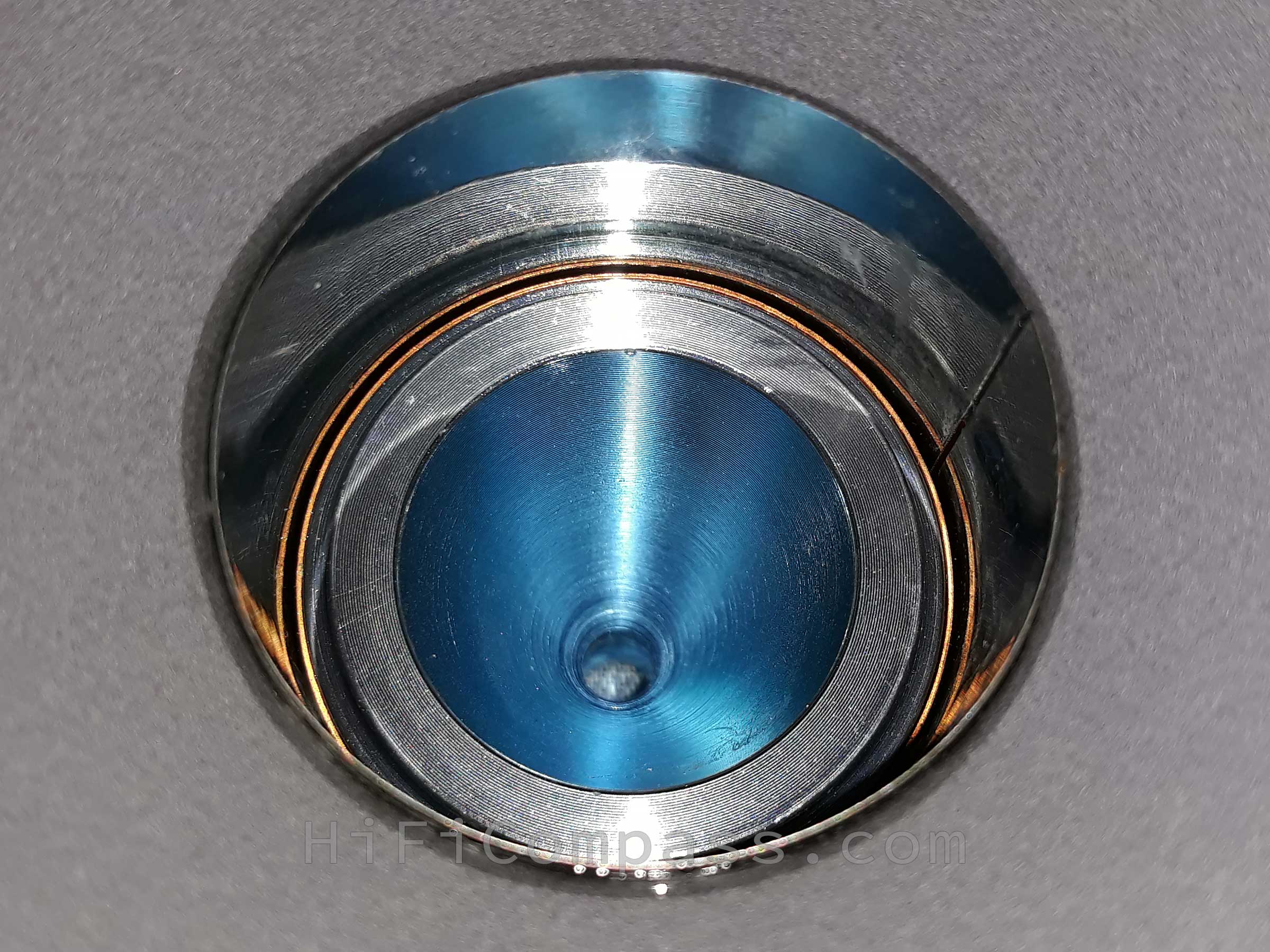
The production quality is just perfect on the front side, there is nothing to complain about. The perfect alignment of the pole piece "bullet" (phase plug) inside the voice coil former, the gap between the surround and the basket rim is as minimal and uniform as possible.But on the back side something is not as perfect as on the front. In the complete absence of any cosmetic defects, burrs and chips, on both samples there are small residues of glue between the magnet and the back plate, misalignment of the glued labels and a noticeable misalignment of the magnet on one of the speakers.
- The cone is made of cellulose and covered with NEXTEL painting on the front side, and with a soft transparent damping compound on the back side. When tapped with a finger, the cone responds with the pleasant sound of well-damped paper.
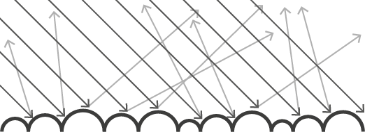
NEXTEL is a truly unique coating (the NEXTEL trademark belongs to the German company Mankiewicz Gebr. & Co. (GmbH & Co. KG)). It creates the feeling of a suide-like surface and is created with special patented pigments of various grains. These pigments increase the surface and create a texture that feels velvety or suede. The combination of colored pigments results in the typical NEXTEL effect of salt and pepper. Due to their size, the pigments are individually visible and give typical NEXTEL colors. In addition, the uneven surface structure results in diffuse light scattering, resulting in a very matte surface that absorbs up to 98% of the incident light.

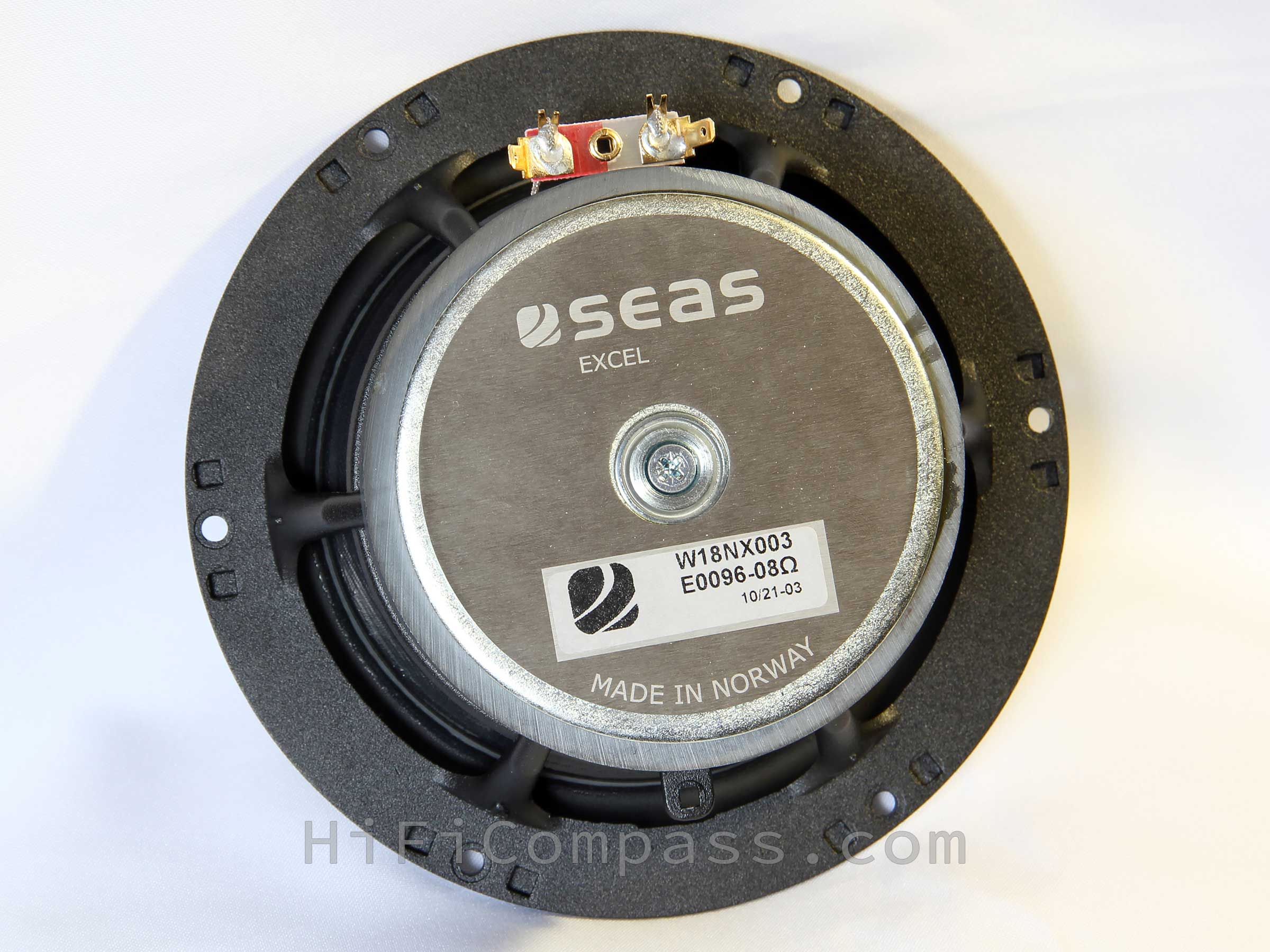
- The basket is made of aluminum alloy and coated with a very durable micro-textured powder coating. The 5.4 mm thick solid mounting flange is held on narrow but solid and strong spokes. Thanks to the huge "windows" between the spokes, the basket is acoustically very transparent, and when you tap it with your finger, it immediately becomes clear that it is absolutely inert. The basket is attached to the top plate of the magnetic system with rivets. Unfortunately, there is no foam gasket on the basket flange and it is also missing from the delivery set. A trifle, of course, but useful and for such a status product there is no sense to save on it.
- The top and bottom plates of the magnetic system are made by conventional stamping. The back plate has a luxury brushed and anodized metal label with a model name sticker and the company logo engraved on it.
- The pole piece "bullet" is all-metal, made by turning and has high-quality matte black anodizing. The bullet is fixed with a screw that runs through the pole piece. It can be detached without difficulty and we get access to the heart of the speaker motor. The speaker design with a phase plug has some pros and cons compare to the design with dust cap:
+ phase plug reduces compression due to temperature variations in the voice coil
+ phase plug increases long term power handling capacity
+ phase plug eliminates resonances in the cavity inside the voice coil former
- phase plug "steals" useful cone radiation area
- such a design reduces the tightness of the loudspeaker enclosure, but this effect can be neglected - The pole piece has a conical recess inside. It is one of the key elements of the magnetic system and is made by turning, as evidenced by clearly visible cutter marks on its surface. There is a copper sleeve around the pole piece and an additional very massive tall copper ring is installed on top of the pole. Now it becomes clear that we are not dealing with a primitive motor, but really a product of modern engineering. Measurements will show how effective these measures are.
- The magnet is an ordinary ferrite one.
- The classical half-roll surround is made of rubber. The edge of surround back side, where it is glued to the cone, is covered by damping compound about of 5 mm width along its circumference. The compound is the same as on the back of the cone. Apparently, this coating determines the essence of the adaptive surround.
- The four-wave spider is made of black fabric with the addition of long reinforcing synthetic microfibers. They serve both to ensure long-term stability of the spider parameters and for its damping.
- The voice coil is two-layer, overhang type, wound with copper clad aluminum wire to reduce the moving mass.
- The voice coil former is made of titanium and has no ventilation holes, since in such a design, without a dust cap, and with a "bullet" on the pole piece, there is simply no need to equalize the excess pressure formed under the cap. This is one of the advantages of "bullet" designs.
- The silver lead wires are quite soft and connected to a simple terminal block on a fiberglass base. The rigidity of the terminal block and contacts could be higher. You need to be careful when connecting the terminals.
So, the visual inspection suggests that we are dealing with a high-end midwoofer in a classic design, but in which a modern "advanced" motor is hidden. The production quality is generally excellent, with the exception of a few, it seems to me, not very critical points.
_impedance_50_Ohm_nonbrokenin%2Btext.png) |
_impedance_10_Ohm_nonbrokenin%2Btext.png) |
_impedance_70_Ohm_brokenin%2Btext.png)
My experience suggests that such a broken-in almost completely softens the speaker suspension and the Thiele-Small parameters already reach steady-state values that can be taken into account when designing a loudspeker enclosure.
The following parameters were obtained for the 18WNX003 (E0096-08) midwoofer:
Fs=49 Hz (35 Hz in the datasheet)
Qts=0.496 (0.34 in the datasheet)
Vas=17.57 liters (31 L in the datasheet)
As you can see, the parameters are radically different from those declared by the manufacturer. The moving mass, taking into account the permissible measurement error, is quite close to the datasheet, therefore, it is obvious that the reason is in the significantly lower compliance of the suspension.
Usually, for the broken-in speakers my measurements of Thiele-Small parameters in a low-signal mode (several milliamperes) using a Dayton Audio WT3 tester either coincide or slightly differ from manufacturers' datasheets. However, there are exceptions, one of which we are seeing now. So what is the reason for such a big discrepancy? Is it just a banal error in the datasheet or a real deviation of the speaker production technology from the designed one? Maybe the question is in a measurement method, as was a case with the Purifi midwoofer? It's the truth, today there really is no single standardized method for measuring Thiele-Small parameters and each manufacturer determines how to measure them on its own.
Claus Futtrup :
Hi Yevgeniy,
The way SEAS measures parameters is described here:
http://www.seas.no/index.php?
option=com_content&view= article&id=406&Itemid=270 Quote: Please be aware that differing power levels and measurement methods may give significantly different fs, and consequently different values for other parameters dependent upon fs.
This means that the SEAS data is not replicated by low-voltage measurements. Nor will they comply with Klippel LPM data. In either case you will often see that the SEAS datasheet has a lower fs and softer suspension. The reason that the suspension becomes a bit softer at higher power input is due to stiction (a word for static friction).
The reason we measure with such a power level is because we believe it is representative for the typical user case, provide some 85 dB of SPL, and therefore our data is more suitable for box simulation.
Following the link, we find the method for measuring the Thiele-Small parameters by SEAS:
Before measuring the T/S-parameters the driver has been run in at near maximum excursion in free air using a sine signal at f0 for 2 min. The resonance frequency and impedance at resonance are measured using a 2 VRMS sine signal.
The moving mass and the BL-product are measured with the laser equipment from Klippel GmbH.
Resonance frequency fs is measured using 2 Vrms sine wave. Please be aware that differing power levels and measurement methods may give significantly different fs, and consequently different values for other parameters dependent upon fs.
Yes, the measurement conditions of the WT3 tester and SEAS are significantly different. SEAS has its own well-founded position on this matter and, I must say, it is very logical. Okay, it remains to check the resonant frequency of the W18NX003 (E0096-08) strictly according to the manufacurer's method. If it matches the datasheet, then the rest of the parameters will also match. I decided to measure Fs not only for 2 Volts, but also to trace its dependence on voltage in the range from 0.1 to 10 Volts in the classical way using a generator, a voltmeter and an additional resistance of 0.1 Ohm. The results are summarized in the table:
| Voltage at the midwoofer, Volt | Resonant frequency Fs, Hz |
| 0.1 | 47 |
| 0.5 | 42 |
| 1 | 39 |
| 2 | 35 |
| 5 | 33 |
| 10 | 37 |
Everything cleared up and the resonant frequency coincided with the datasheet just perfect! So, the manufacturer is not lying![]() . The dependence of Fs on voltage is very indicative and the value given in the datasheet really corresponds to the most probable condition of the midwoofer operation in a loudspeaker.
. The dependence of Fs on voltage is very indicative and the value given in the datasheet really corresponds to the most probable condition of the midwoofer operation in a loudspeaker.
Since there is such a freedom in the industry in determining the Thiele-Small parameters, it is interesting to see how other leading manufacturers look at it. The information below is taken from the official websites of the companies:
Wavecor measures using a semi-constant current source, nominal level 2 mA. After burn-in specifications are measured 12 hours after exiting the transducer by a 20 Hz sine wave for 2 hours at level 10/14.1 VRMS (4/8 ohm version).
SB Acoustics - "A lot can be said about how to measure loudspeaker Thiele/Small parameters. There are different methods of measurement and they are not all equally good (this will not be discussed here). Due to drive unit non-linearities, there is not one final set of parameters for any drive unit. Several of the parameters are a function of cone/voice coil excursion, hence they depend on the input voltage/current level. At SB Acoustics we use the delta mass method (as opposed to delta compliance). We use a constant voltage source and a 150 Ω resistor in series with the drive unit. Hence, this is neither a constant voltage nor a constant current measurement (the value of the resistor is not nearly large enough to approximate constant current, which is not the intention either). Prior to measuring T/S parameters, the drive unit should be broken in – for two reasons. If the suspension of the drive unit is not broken in, its compliance will slightly increase during the measurement, thus affecting/distorting the results. Furthermore, eventually the drive unit will end up being broken in (it actually does not take that long), which is why it is recommended to use T/S parameters that apply for a broken-in drive unit when calculating box volumes and tuning frequencies. The free air resonance frequency typically drops about 10-15% during break-in, as the suspension compliance increases. This directly affects the Q-factors and the equivalent volume. To break in a drive unit, you are going to need a sine wave or a noise generator with adjustable output voltage (the former is recommendable) and a power amplifier. Using a sine wave generator, adjust the frequency somewhere below the expected free air resonance frequency of the drive unit (typically about 80% of this value). Slowly turn up the voltage until the suspension reaches maximum displacement. Keep it below clipping level. Usually you can hear when the suspension goes into clipping mode - there will be some kind of mechanical noise. Adjust the voltage slightly below this level. During the process of breaking in the drive unit, it might be necessary to turn down the voltage a little to keep it from clipping, as the suspension softens. It needs to run for about ten minutes. Before measuring, let the drive unit cool to ambient temperature. The voltage that should be applied to the terminals of the drive unit depends on its size/type. For a typical mid-woofer, the voltage should be about 1 V (rms) at the resonance frequency.
Scan-Speak - "Measurement of Thiele/Small parameters can lead to quite a bit of discussion within the loudspeaker community. The following is a description of the method used at Scan-Speak. The initial description of measurement and calculation of these Small Signal Parameters comes from Richard Small’s papers in the Journal of Audio Engineering in 1972, “Direct Radiator Loudspeaker Analysis”. Both Neville Thiele’s and Richard Small’s papers on this subject dealt with alignment of bass response for loudspeaker systems. It is really important to understand that we are working with “small signal” parameters, which means that the excitation of the moving parts is so small that the mechanical properties can be considered to operate in their linear range. It is also important to realize that any small change of measurement method will result in different results. In fact, there are different ways of measuring these parameters in the market, and they are being used by different systems manufacturers to align or tune loudspeaker systems. So there is no one “correct” set of parameters, but several sets that could potentially be used and the key is to stick with one method and evaluate whether the resulting system response matches your simulation results.
We use the classical simplified model and the measurement by Scan-Speak’s R&D follows Richard Small’s derivation of the parameters. We use very low excitation and obtain constant current by using a compressor to maintain a constant voltage over a series resistor. We use pure sine tones from an analog generator and search the resonance frequencies, the side frequencies and the voltages manually. We use the “added mass” method, and choose an added mass big enough to get a large enough difference in resonance frequency.
Before starting measurement of the parameters, the drive unit must be burned-in by exposing it to a (preferably) sine tone at a frequency slightly below or at the initial resonance frequency and then applying a voltage large enough for the driver to move almost to its maximum excursion. If the driver starts clipping, which is clearly audible, turn back the voltage. The T/S parameters should always be measured on a burned-in driver, because the compliance of a completely new driver will change quite a bit in the first few minutes of excitation. So if the data is to be used for system design, the burned-in dataset is the useful one.
B&C Speakers - Applied RMS Voltage is set to 2.83 V for 8 ohms Nominal Impedance. Thiele-Small parameters are measured after a high level 20 Hz sine wave preconditioning test.
Eighteen Sound - Applied RMS Voltage is set to 2.83 V for 8 ohms Nominal Impedance. Thiele-Small parameters are measured after a high level 20 Hz sine wave preconditioning test.
From the "Summary" part of the W. Klippel, U. Seidel, KLIPPEL GmbH Germany "Fast and Accurate Measurement of Linear Transducer Parameters" article - Despite linear parameters are straight forward and appealing they are meaningless in the large signal domain. As some parameters (see figure 13) are not constant and vary even at small amplitudes the question arises: “What is the small signal domain ?”. Linear modeling of the mechanical suspension seems to be an inadequate simplification of the reality. The dynamic behaviour of the suspension depends not only on the instantaneous displacement but also on the peak displacement occurred in the last period of time. Although it is convenient and common practice to express compliance CMS and resonance frequency fs by single numbers this information shows only a small part of the whole picture. The “single number” linear parameters can be interpreted as weighted mean values of the corresponding nonlinear parameter curves. However there is no contradiction between linear and large signal parameters. There is in fact a smooth connection as large signal parameters preserve and generalize the linear parameters. The large signal parameters give additional information valuable for assessing the permissible working range (maximal displacement, maximal power) and the permissible mechanical and thermal load. Furthermore the large signal parameters reveal the dominant sources of distortion.
As you can see, not everything is as simple as it might seem at first glance![]() .
.
Thanks to the excellent motor with a copper sleeve on the pole piece, the impedance has very low inductance and shows little rise with frequency. The response is very smooth, without pronounced resonances, but only with a slight waviness in the range from 800 Hz and above, which is a typical behavior of soft membranes. This waviness is very insignificant and is noticeable only with a large scaling. This indicates excellent membrane damping.
The reason for the appearance of a small bump in the region of 450 Hz on the impedance remains unclear; it is possibly related to the resonance of the lead wires.
The impedance response tells us about an excellent motor, very good balanced and damped moving system.
On-axis frequency response
-Smoothed-SPL-Frequency-Sample-%231-and-%232.png)
The on-axis frequency response smoothly rises up to 2.5 kHz. The average sensitivity in the range up to 1 kHz is close to the datasheet and is about 87-87.5 dB.
The curve is very smooth throughout the entire range, without sharp deep peaks and dips. In the critical region between 800 Hz and 2 kHz, which is typical for an edge/surround resonance of soft cones, the frequency response behavior is exemplary - the engineers managed to solve this problem. The main culprit behind this good behavior is the SEAS adaptive surround.
In the range 2.5 - 7 kHz a smooth and wide hump with a height of about 8 dB is observed. It is typical behavior of paper cones in combination with a very low inductance motor. Nothing critical, the hump is smooth and well controlled, which is a sign of well damped cone.
Near of 400 Hz there is a shallow dip of 1 dB. This is not an artifact of measurements, but a real fact. I can't explain its true cause, but can suggest it may be related to the lead wires resonance. Remember the impedance response near 450 Hz.
Due to very smooth range up to 2.5 kHz the frequency response does not imply any difficulties when designing a loudspeaker crossover. It is a pleasure to work with such a speaker.
The responses of the two samples are identical to each other over the entire range, which is especially remarkable and hard to achieve with paper cones!
The measured frequency response is in good agreement with the datasheet. Excellent!
Off-axis frequency responses (315 mm)

The measured off-axis frequency responses are in good agreement with the datasheet. Excellent!
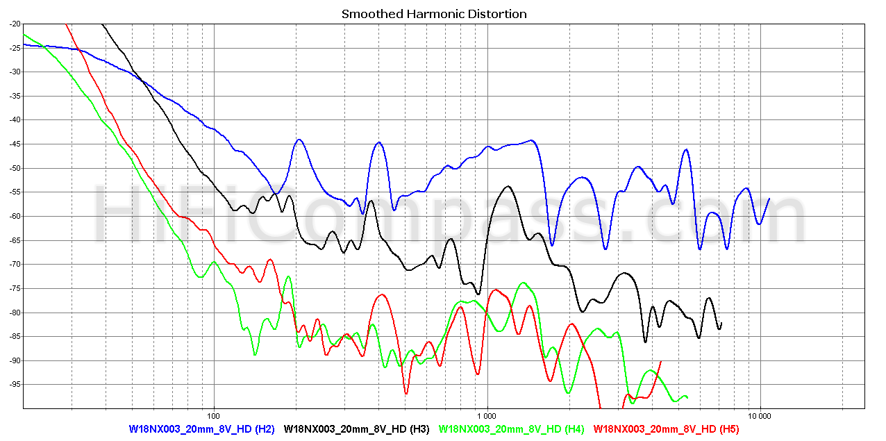
Harmonic distortion (315 mm)
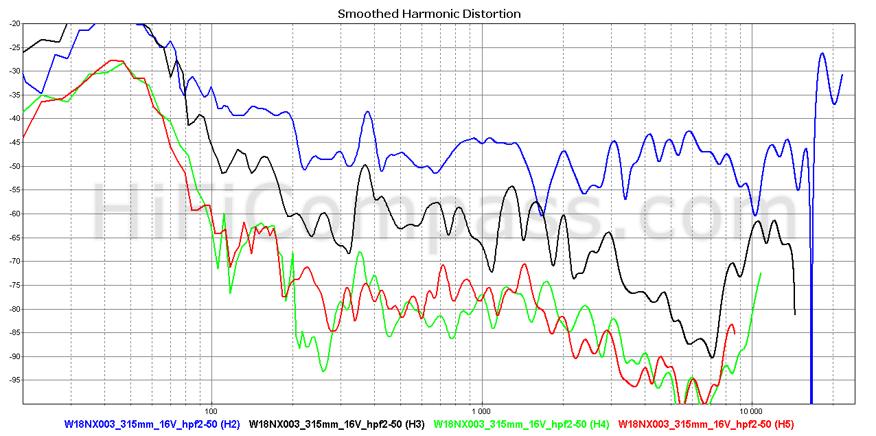
Above are the harmonic distortions plots for the 2nd - 5th harmonics at average sound pressure levels of 87.5 and 102.5 dB (at voltages of 2.83 and 16 Volt respectively). To limit the speaker overload in terms of thermal power and membrane displacement when measuring harmonic distortion, a second-order Butterworth type high-pass filter with a cutoff frequency of 50 Hz was used. On these graphs we analyze the frequency range only from 200 Hz and above.
The second harmonic dominates the entire frequency range and at all sound pressure levels. The third harmonic goes several dB lower, and the fourth and fifth even lower with a large margin. The harmonic distortion pattern is stable at both frequency and SPL. There are no sudden abrupt jumps in distortion over the entire range due to the membrane break-up, especially at high SPL. In the 700 Hz to 2 kHz range, where soft diaphragms tend to have distortion problems due to the cone edge resonance, everything is clear even at 102.5 dB SPL. There is a small burst of harmonics of all orders at all sound pressure levels around 400 Hz.
I would rate the harmonic distortion above 200 Hz as "very low", one of the lowest I have ever seen in 6" midwoofers. Excellent!
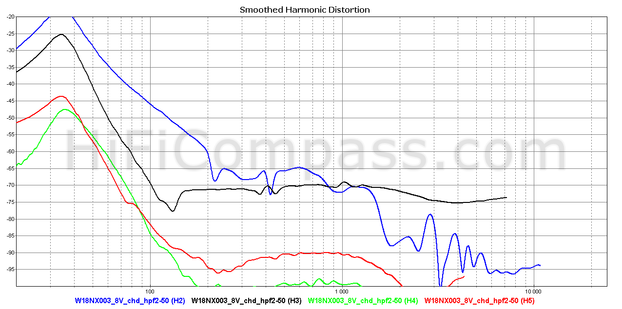
Harmonic distortion (5mm - 20 mm)
The 2nd harmonic dominates in the range from 40-50 Hz up to 200 Hz. With decrease in frequency all harmonics increase monotonically, their behavior and hierarchy below 200 Hz are the same as above 200 Hz.
I would rate the harmonic distortion at low frequencies as "low".
Voice coil current harmonic distortion
This type of measurement, despite its simplicity, is an excellent tool for assessing the linearity of a speaker motor. The above plots show the frequency dependences of the 2nd, 3rd, 4th and 5th harmonics of the voice coil current at 2.83 and 8 Volt. To limit the speaker overload in terms of the membrane displacement when measuring harmonic distortion, a second-order Butterworth type high-pass filter with a cutoff frequency of 50 Hz was used.
Voice coil current nonlinearity is the direct nonlinearity of the mechanical force driving the speaker cone, since this force is related to the current by a simple relationship F=B*L*I, where B is the magnetic field strength, L is the length of the voice coil wire inside the magnetic gap and I is the current. So, in principle, it is practically impossible to obtain sound pressure distortion lower than current distortion in the frequency range where the contribution of the motional nonlinearity becomes insignificant.
The fourth and fifth harmonics above 100 Hz can be ignored, their level is very low and stable regardless of excitation. The second harmonic of the current at low voltages goes under the 3th one, but confidently outruns it when the voltage goes up. The 2nd harmonic linearly depends on the voltage level, as well as its manifestation in sound pressure. Above 100 Hz the 3rd harmonic stays practically independent of the input voltage. Below 130 Hz, due to an increase in the membrane displacement amplitude, a sharp increase in harmonics of all orders begins.
I would rate the voice coil current harmonic distortion "low/very low", one of the lowest I have ever seen in 6" midwoofers. Excellent!
Intermodulation distortion
The intermodulation distortion measurement is one of way of analyzing device non-linearity. It is not an alternative, but an additional method and allows you to identify the spectral components of the inharmonious structure, which are much more harmful for high-quality sound reproduction and to which our hearing is more sensitive.
- test frequencies
- 2nd order harmonic distortion components for the test frequencies (2nd HD)
- 3rd order harmonic distortion components for the test frequencies (3rd HD)
- 2nd order intermodulation distortion amplitude (IMA2)
- 3rd order intermodulation distortion amplitude (IMA3)
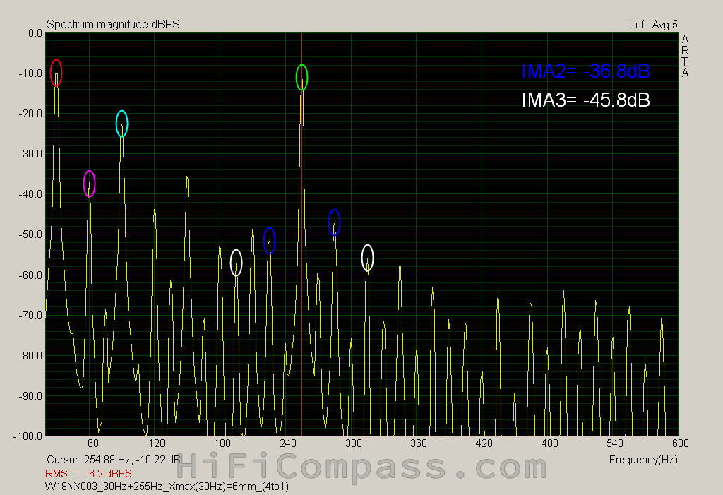
As you can see, just a couple of frequencies at the speaker terminals give rise to a whole forest of parasitic components at its output. The levels of second order intermodulation components are -41.77 dB and -36.8 dB for cone excursions of 3 mm and 6 mm respectively. I must say that the result is great! These numbers coincide with the Doppler distortion threshold. This means the main cause of parasitic spectral components is frequency modulation, which is fundamentally unavoidable for speakers and has nothing to do with the speaker motor quality. The Doppler distortion threshold limits the achievable lower measurement limit for the motor's BL modulation induced distortion. So, the real distortion of the W18NX003 (E0096-08) motor is possibly even lower than the obtained values. So far, I have measured such a low level of IMD distortion only in one midwoofer - Purifi PTT6.5W08-01B. Bravo, SEAS!
Step response
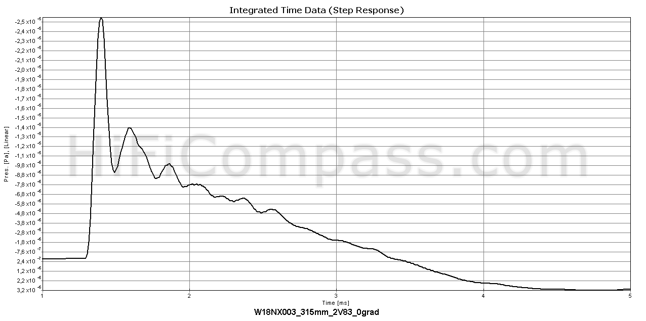
The step response exhibits excellent slew rate and smooth aperiodic decay. The decaying oscillations in the falling part of the response are due to the cone resonance in the 4 kHz region.
Waterfall
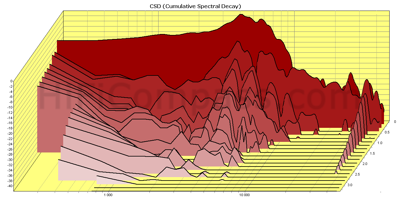
The waterfall shows the same effects as a step response, in addition exposing hidden resonances that are difficult to see in other types of measurements.
At 4 kHz we observe a ridge from the main resonance of the cone, which completely disappears in just 2.5 ms. Otherwise, everything is fine, the moving system calms down very quickly and there are no any problems in the 700 Hz - 2 kHz region.
Listening impressions
As usual, the logical completion of my measurement program is listening to the speaker in the test baffle in order to get the first subjective impressions about the character of the speaker sound. It is extremely difficult to describe the sound of the speaker driver in words, since there is no single generally accepted terminology. In addition, everyone hears and describes their feelings in different ways. Much depends on the accumulated experience of listening and the number of "sound prints" of various speakers stored in the head. It is no less difficult to understand, feel and imagine a sound described by someone. This requires that describing and imagining people are in the same coordinate system and have a common reference point.
I listened to the W18NX003 (E0096-08) midwoofer both without any frequency response correction, as it is, and with the correction to a "ruled flat" one with use of a digital signal processor. In the last case, the slowly growing of the frequency response and the hump at 5 kHz were fully corrected.
Being familiar with many of SEAS paper cone midwoofers, I instantly recognized distinctive SEAS sounding - warm, soft, enveloping sound with a very sensuous midrange, moderately detailed and transparent. You want to wrap yourself up in it, like in a winter cold in a warm cashmere blanket. This sound cuts off all sharp corners and never hurts with any unexpected squeal. Smooth, flowing, velvety and natural. Similar in character to the sound of the SEAS midwoofers with paper cones covered with a damping compound - CA12RCY, CA15RLY, CA18RLY, CA18RNX, CA22RNX, W12CY003, W15LY001, W18NX001, but far from uncoated reed/paper cones as ER18RNX, ER15RLY. If we compare with the predecessor W18NX001 (E0042-08S), then, if my memory serves me, the sound is the same, the only difference is that the W18NX003 (E0096-08) better holds the overload at high volumes, while maintaining transparency and intelligibility. So, when upgrading the loudspeakers in which the W18NX001 (E0042-08S) are installed, you can absolutely not worry about the risk of losing your familiar and favorite sound.
The bass performance is very clean in terms it is absolutely free of any chuffing and air noise. Very few midwoofers can boast of such a quiet motor.
"How to use" recommendations
Considering the price, outstanding technical characteristics and positioning the W18NX003 (E0096-08) midwoofer by the manufacturer as one of its top-end ones, its optimal use will be as a midwoofer in 2 and 2.5-way, as well as a midrange in large 3-way loudspeakers of the highest price and quality segment in the frequency range up to 3 kHz.
I did a litle simulation of the "closed box" and "bass reflex" designs in the VituixCAD miracle program using the Thiele-Small parameters from the datasheet - Fs=35 Hz, Qts=0.34, Vas=35 liters.
For the "closed box" design the maximum flat frequency response (Qtc = 0.707) is obtained in a volume of 10 liters, while the lower cutoff frequency is 72 Hz at a level of minus 3 dB. The maximum sound pressure without overload at low frequencies is 102.5 dB. It is unlikely that this type of design will be popular for the W18NX003 (E0096-08), rather as an option for those who like very "dry" but articulated bass.
For the "bass reflex" design the optimal volume turned out be in the range from 15 to 18 liters, while the lower cutoff frequency is obtained from 47.6 Hz to 43.6 Hz, respectively. In a smaller enclosure the bass depth is exchanged for a greater overload capacity. As a result, we have not super deep, but dense punchy bass with pure sound pressure of up to 104 dB in the range above 200 Hz - this is no joke for a two-way loudspeaker! What more could you want?
The simulation results are shown below:
Closed box, 10 liters
_orig_closed_10_ liters Six-pack%2Btext.png)
Bass reflex, 15 Liters_orig_vented 15 liters Six-pack%2Btext.png)
Bass reflex, 18 Liters_orig_vented 18 liters Six-pack%2Btext.png)
What is the price and where to purchase it?
The W18NX003 (E0096-08) midwoofers are already on the market. The retail price is €318-330 per piece excluding VAT. It can be purchased in the following online stores:
- https://audio-hi.fi/en/seas_e0096-08-p-5224.html
- https://www.soundimports.eu/en/seas-w18nx003.html
- https://en.toutlehautparleur.com/pair-of-speaker-seas-w18nx003-8-ohm-176-mm.html?___store=tlhp_en&___from_store=v2
- https://solen.ca/products/speakers/home-speakers/woofers/seas-excel-w18nx003-e0096-18cm-nextel-cone-titanium-vc-woofer/
Summary
The W18NX003 (E0096-08) has become a worthy successor to the SEAS Excel W18NX001 (E0042-08S) midwoofer, which has gained immense popularity over the past 15 years. By retaining the sound signature, it has taken a big step forward in terms of the linearity of the magnetic system and increased overload capacity. The W18NX003 (E0096-08) comparing with the W18NX001 (E0042-08S) has the next principal improvements:
- much more long term power handling, 200 W vs 80 W
- much lower inductance, 0.13 mH vs 0.43 mH
- lower electromechanical loss, Qms=3.11 vs 2.08
- much more linear motor
Harmonic distortion in the entire frequency range is very low, at the level of the best modern midwoofers. The intermodulation distortion turned out quite surprising - on the same level as the best midwoofer in the industry known to me, the Purifi PTT6.5X08-NFA-01B. So, despite its classic and conservative design, the W18NX003 (E0096-08) has state-of-the-art performance.
Based on the measurements and listening results, I consider the W18NX003 (E0096-08) one of the best regardless of price available 6" midwoofers in the world today.
Summarizing the above, I can highlight the following:
- Average sensitivity is from 87 to 88 dB/2.83 V*1 m
- Very smooth frequency response
- Very low harmonic distortion throughout the entire frequency range
- Very low intermodulation distortion
- It can be used up to 3 kHz
- Good agreement between the measured parameters and the datasheet
- Excellent manufacture quality on the front side, but could be better on the back side
You can get more information about the measurement results here
Yevgeniy Kozhushko/05.07.2021


CONTACTS
- Ukraine
- (+380) 95 904 7827
- hificompass@gmail.com
LAST NEWS
-
27 Mar 2025
-
04 Mar 2025
-
25 Feb 2025
-
10 Feb 2025

Comments (1)
This W18NX003 seems to have a similar motor as our new LINKWITZ22MG (by SEAS), a dedicated 8" upgrade driver for Siegfried Linkwitz´ LX521 in the LowerMid position (120Hz-1000Hz) . https://linkwitz.store/product/linkwitz-22mg/
I can confirm the very low 3rd order harmonic distortion measurements with this SEAS motor. (2nd order hd are extremely low as well). 2nd and 3rd order HD should be below the threshold of human perception.
I wonder if there are any other 6.5"-8" drivers around, that could match the distortion performance of SEAS W18NX003, LINKWITZ22MG or Purifi PTT6.5 ?
Cheers, Frank